Heat-dissipating fin assembly for heat sink

Inactive Publication Date: 2006-01-19
HON HAI PRECISION IND CO LTD +1
View PDF8 Cites 3 Cited by
  • Summary
  • Abstract
  • Description
  • Claims
  • Application Information

AI Technical Summary

Benefits of technology

[0006] Accordingly, what is needed is a heat sink having a heat-dissipating fin assembly which removes hea

Problems solved by technology

If the chip is unable to transfer enough heat to ambient air, the elevated operating

Method used


Image

  • Heat-dissipating fin assembly for heat sink
  • Heat-dissipating fin assembly for heat sink
  • Heat-dissipating fin assembly for heat sink

Examples


Example

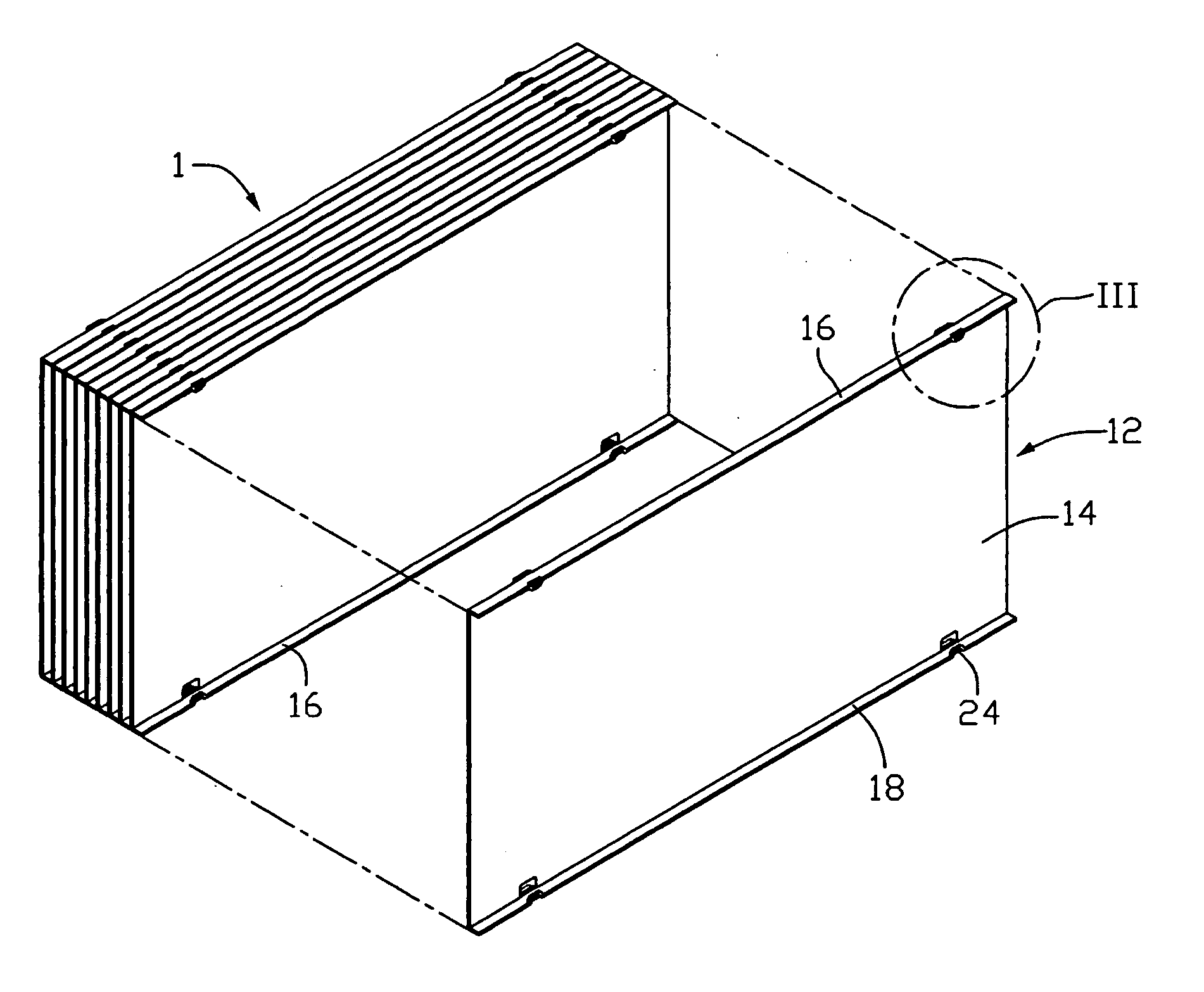
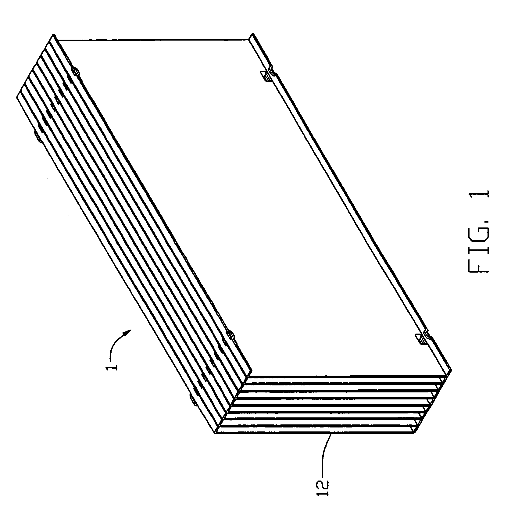
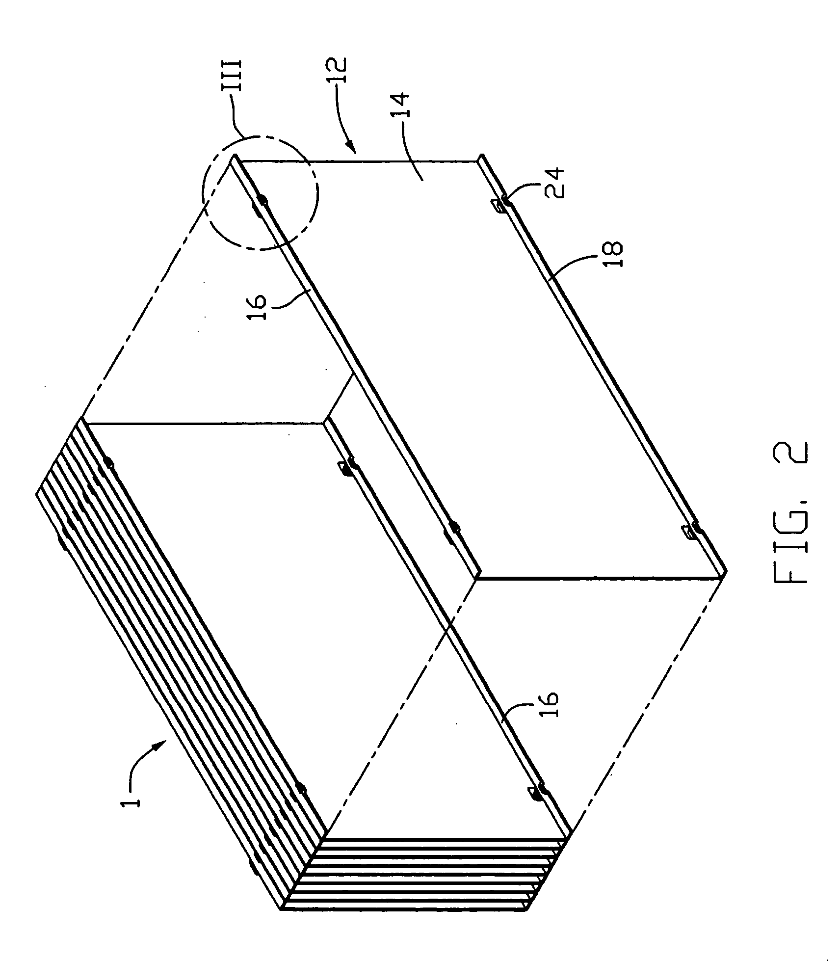
[0016] Referring to FIGS. 1-4, a heat-dissipating fin assembly 1 of a heat dissipating assembly in accordance with a preferred embodiment of the present invention comprises a plurality of individual fin plates 12 arranged side by side.

[0017] Each fin plate 12 is made of a highly thermal conductive material such as aluminum or copper, and is formed by stamping to have a main body 14. First and second flanges 16, 18 extend perpendicularly in a first direction from opposite top and bottom edges of the main body 14 respectively. A pair of spaced first bridge-shaped tabs 20 extends perpendicularly from a distal end of the first flange 16 toward the second flange 18, and a pair of first slots 22 is defined in the first flange 16 above the tabs 20, respectively. A pair of spaced second bridge-shaped tabs 24 extends perpendicularly from a distal end of the second flange 18 toward the first flange 16, and a pair of second slots (not labeled) is defined in the second flange 18 below the tabs...


PUM


Abstract

A heat-dissipating fin assembly (1) includes a plurality of individual fin plates (12) arranged side by side. Each fin plate includes a main body (14). First and second flanges (16, 18) extend perpendicularly from opposite edges of the main body of each fin plate. A pair of spaced first bridge-shaped tabs (20) extends perpendicularly from the first flange toward the second flange. A pair of spaced second bridge-shaped tabs (24) extends perpendicularly from the second flange toward the first flange. Projections (28) are stamped from the main body opposing to the first and second bridge-shaped tabs. The tabs of each fin plate are interlocked with the projections of an adjacent fin plate. In this manner, all the fin plates are assembled together. The heat-dissipating fin assembly is thus formed.

Description

BACKGROUND [0001] 1. Field [0002] The present invention relates to a heat sink for removing heat from heat-generating electronic devices, and more particularly to a heat-dissipating fin assembly of a heat sink with high density fins that are interlocked together. [0003] 2. Related Art [0004] An integrated circuit chip is widely used in an electrical apparatus such as computer. When the electrical apparatus operates, the chip generates heat. If the chip is unable to transfer enough heat to ambient air, the elevated operating temperature may result in damage of the chip or the breakdown of the whole apparatus. In order to remove most heat generated from the chip, a heat sink is usually provided and attached on the top surface of the chip. Generally, the heat sink is provided with a flat base for contacting with the chip and fins for dissipating the heat of the chip into air. The fins can be classified into two types: one is integrally formed with the base by extrusion, and the other i...

Claims


Application Information

Patent Timeline
IPC IPC(8): H05K7/20G06F1/20H01L23/34H01L23/367
CPCH01L23/3672H01L2924/0002H01L2924/00
Inventor LEE, HSIEH-KUNXIA, WAN-LINCHEN, BAO-CHUNLI, NENG-BIN
Owner HON HAI PRECISION IND CO LTD
Why Eureka
Try Eureka