Battery assembly having a heat-dissipating and heat-emitting functions

Inactive Publication Date: 2013-09-12
LG HAUSYS LTD
View PDF1 Cites 42 Cited by
  • Summary
  • Abstract
  • Description
  • Claims
  • Application Information

AI Technical Summary

Benefits of technology

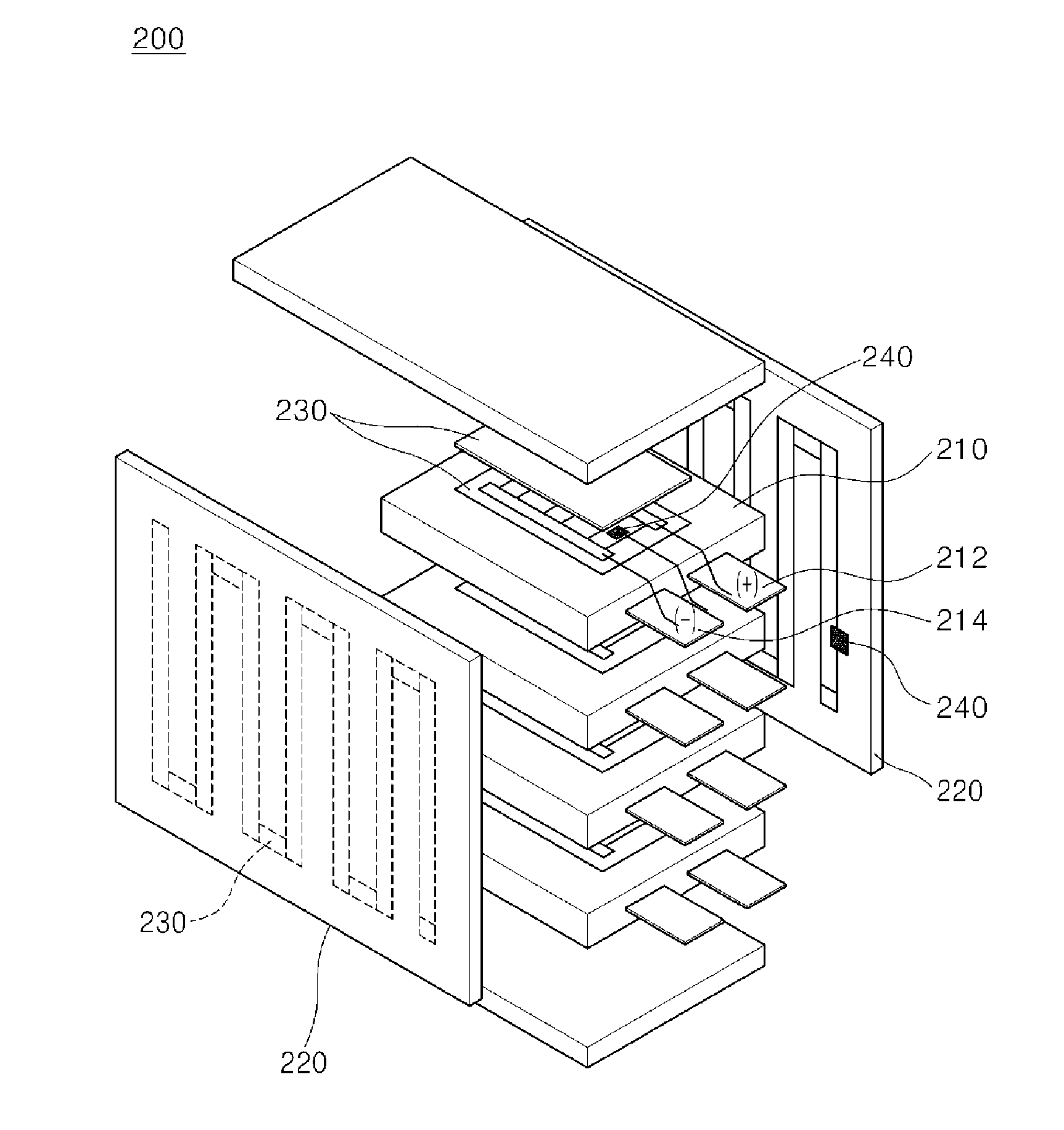
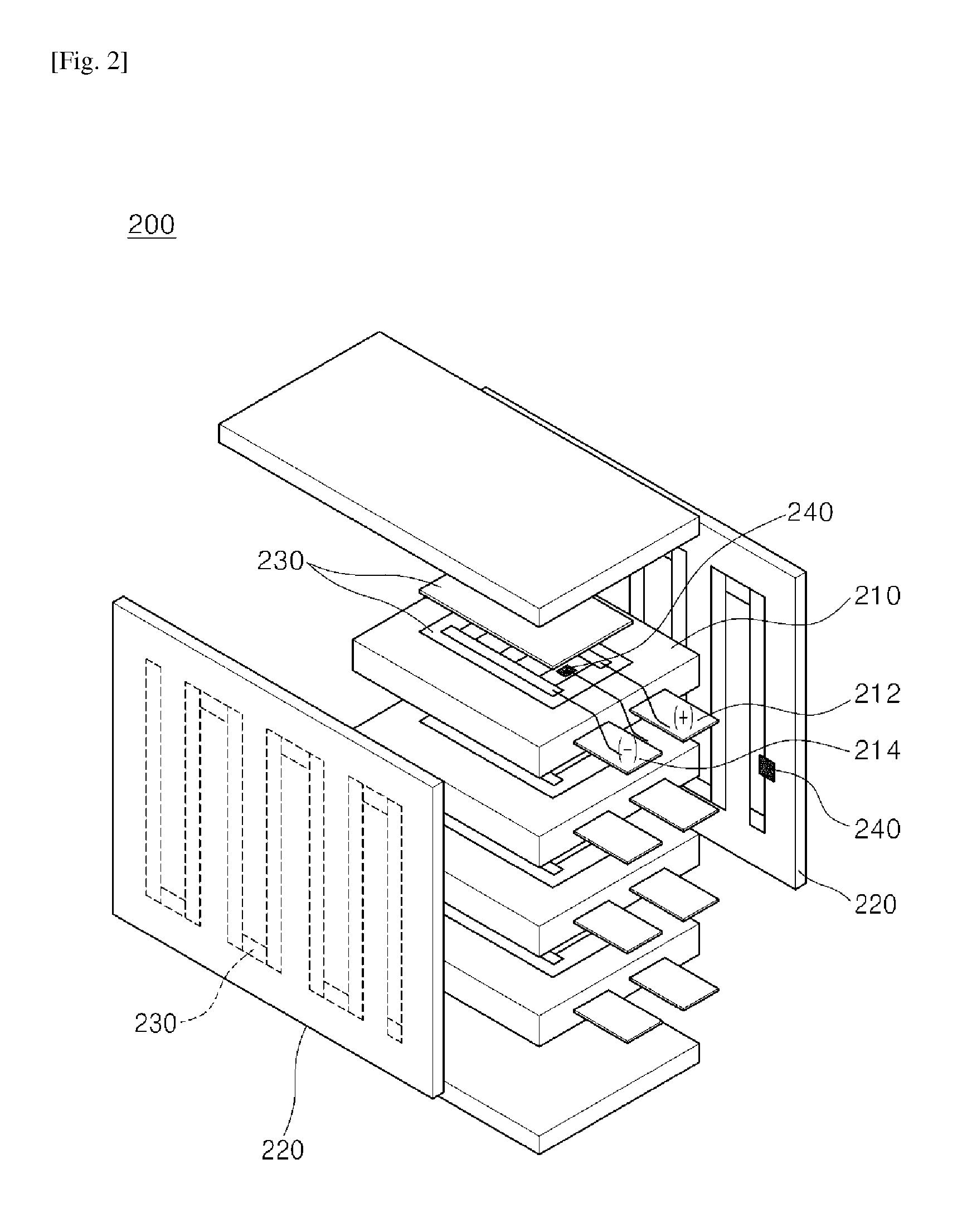
[0027]According to one embodiment of the present invention, there is provided a battery assembly having heat-dissipating and heat-emitting functions, in which a heat-dissipating and heat-emitting film having a carbon nanotube heating body is coated on a battery module and/or an exterior case, and electrical and heat-conductive characteristics of the coated carbon nanotubes are maximized, thereby providing both the heat-dissipating and heat-emitting function at the same time.
[0028]According to one embodiment of the present invention, there is provided a battery assembly having heat-dissipating and heat-emitting funct

Problems solved by technology

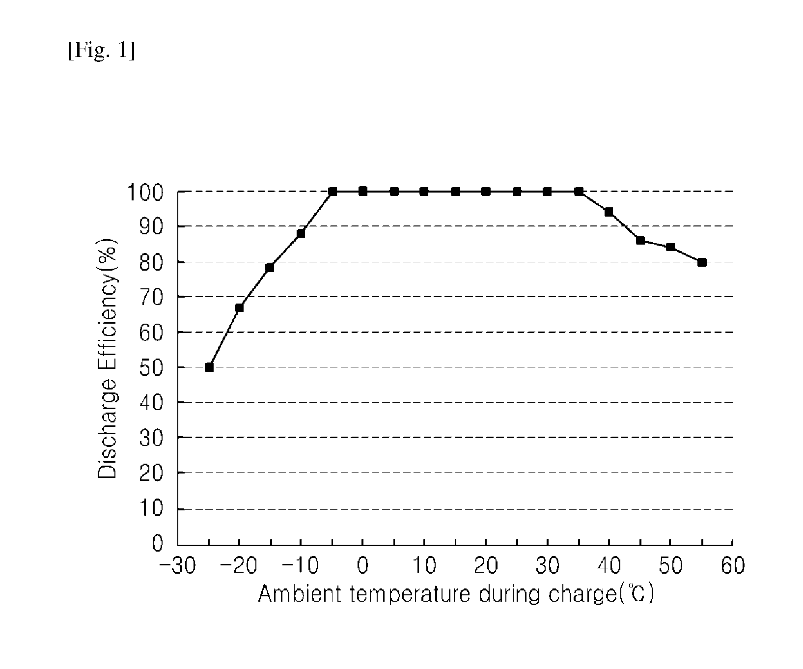
Existing heaters have high initial inrush current, which results in at least twice as much current consumption as the heaters need, and are configured to supply heated air, thereby causing significant reduction in charge capacity of a battery due to heat ge

Method used


Image

  • Battery assembly having a heat-dissipating and heat-emitting functions
  • Battery assembly having a heat-dissipating and heat-emitting functions
  • Battery assembly having a heat-dissipating and heat-emitting functions

Examples


Example

Example 1

[0089]A carbon nanotube heating body and an Ag electrode layer were printed on a base layer composed of biaxially oriented polyethylene terephthalate (BOPET). The carbon nanotube heating body was formed by doping Ag on the surfaces of carbon nanotubes. Next, with a first heat-dissipating layer placed below the electrode layer, an insulating layer composed of an acrylic adhesive was interposed therebetween, and the base layer on which the electrode layer and the carbon nanotube heating body were printed was attached to the first heat-dissipating layer.

[0090]Next, with a second heat-dissipating layer placed on the other side of the base layer, a silicone adhesive layer was interposed therebetween, and the base layer adhered to the first heat-dissipating layer was attached to the second heat-dissipating layer.

Example

Example 2

[0091]A carbon nanotube heating body was printed on a base layer composed of biaxially oriented polyethylene terephthalate (BOPET). The printed carbon nanotube heating body was coated with a Cu electrode layer. The carbon nanotube heating body was formed by doping Cu on the surfaces of carbon nanotubes. Next, with a first heat-dissipating layer placed below the electrode layer, an insulating layer composed of an acrylic adhesive was interposed therebetween, and the base layer on which the electrode layer and the carbon nanotube heating body were printed was attached to the first heat-dissipating layer.

[0092]Next, with a second heat-dissipating layer placed on the other side of the base layer, a silicone adhesive layer was interposed therebetween, and the base layer adhering to the first heat-dissipating layer was attached to the second heat-dissipating layer.

Example

Comparative Example 1

[0093]A sample was manufactured in the same manner as in Example 1 except for a carbon nanotube heating body was not included therein.


PUM


Abstract

According to one embodiment of the present invention, a battery assembly comprises: a battery module comprising a plurality of unit batteries; an exterior case for housing the battery module in an internal space; and a heat-dissipating film which is inserted between the plurality of unit batteries and fitted tightly against each of the plurality of unit batteries, and is attached to the inside surface of the exterior case; and the heat-dissipating film comprises: first and second heat-dissipating layers which are formed of a thermally conductive material and discharge the heat of the unit batteries; and an adhesive layer which is formed between the first and second heat-dissipating layers and adheres the first and second heat-dissipating layers.

Description

TECHNICAL FIELD[0001]Embodiments of the present invention relate to battery assemblies having heat-dissipating and heat-emitting functions.BACKGROUND ART[0002]In existing hybrid vehicles, a hot-wire heater or a ceramic-based positive temperature coefficient (PTC) heater is separately mounted to supply hot air, which is heated by the heater as needed, via a fan, thereby improving battery efficiency.[0003]Existing heaters have high initial inrush current, which results in at least twice as much current consumption as the heaters need, and are configured to supply heated air, thereby causing significant reduction in charge capacity of a battery due to heat generation and high initial current consumption in an initial operation stage. Further, in pure electric vehicles, the charge amount of the battery directly affects operation efficiency, so that the existing heaters are not suitable for such electric vehicles.[0004]Thus, one embodiment of the present invention provides a battery asse...

Claims


Application Information

Patent Timeline
IPC IPC(8): F28F21/02H01M10/50H01M6/50H01M50/209H01M50/224H01M50/227
CPCH01M10/5004H01M10/5032H01M10/5055H01M2/1077H01M10/5006H01M10/5016B82Y40/00H01M10/5083H01M2220/20F28F21/02H01M6/5038C01B31/0253B82Y30/00H01M10/5053H01M10/625H01M10/615H01M10/647H01M10/6571H01M10/6555H01M10/6554C01B32/168H01M10/613Y02E60/10H01M50/227H01M50/209H01M50/224H01M10/6551H01M10/653H01M10/655H01M10/486H01M10/635H01M50/20H01M10/63
Inventor YUE, SEONG-HOONLEE, MIN-HEEJUNG, YONG-BAE
Owner LG HAUSYS LTD
Why Eureka
Try Eureka