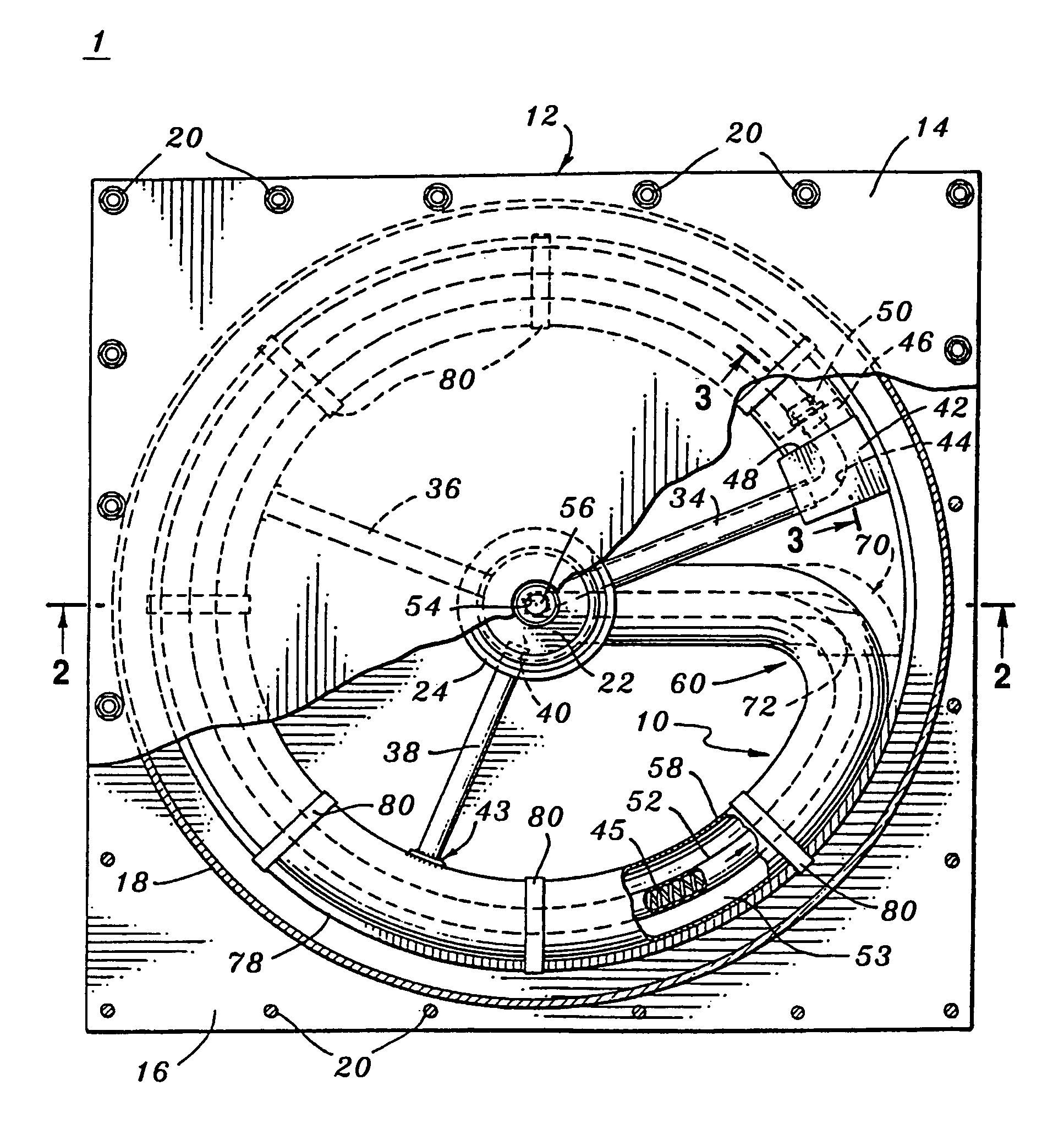
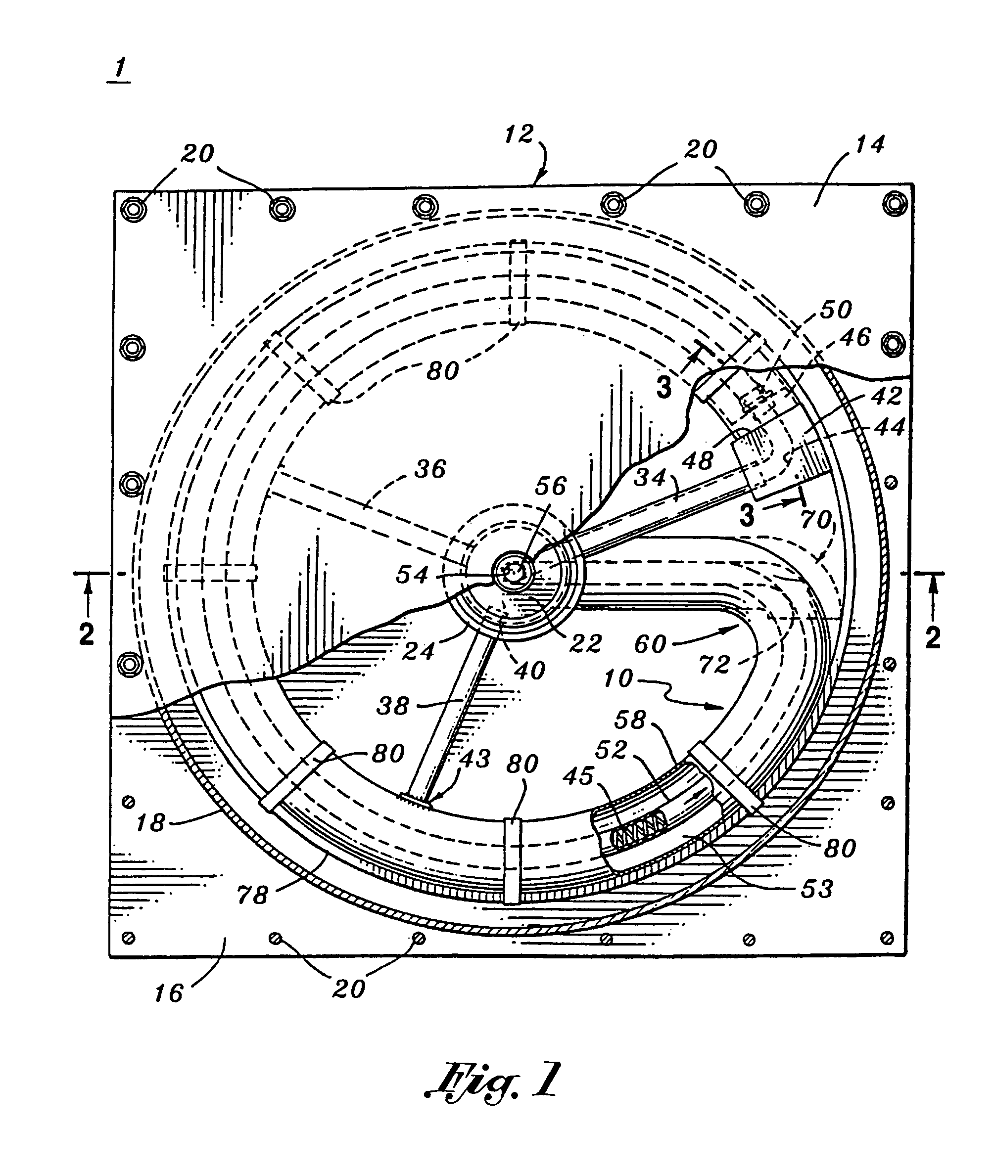
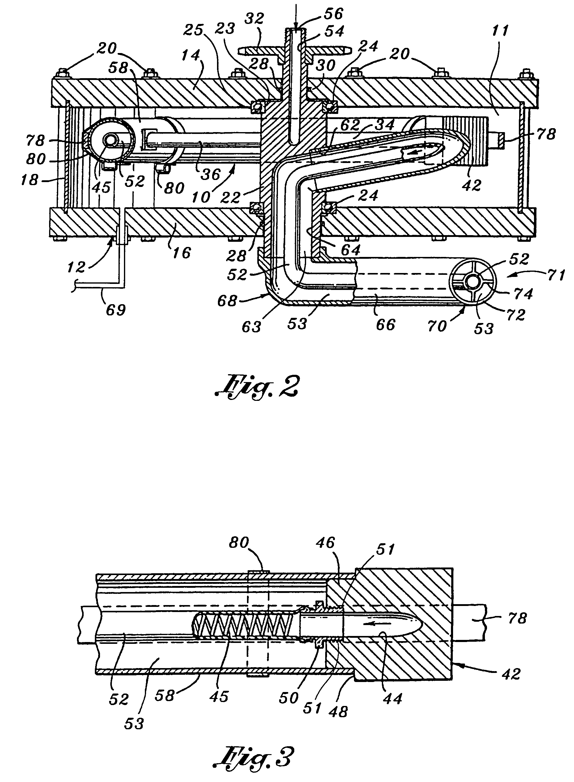
Gas-jet driven rotary device for generating a field and a process for treating items within the field for increased performance
- Summary
- Abstract
- Description
- Claims
- Application Information
AI Technical Summary
Benefits of technology
Problems solved by technology
Method used
Image
Examples
example i
[0047]The first example is included to illustrate the effect and / or impact of the field generated by the rotary device 1 on lead storage batteries 114 charged within the field proximate the rotary device 1 (see FIG. 6). The first example also analyzes the impact of the field on the battery charger 112 itself (see FIG. 6), and on the battery charging techniques utilized to charge the lead storage batteries 114.
[0048]FIG. 6 schematically shows the bank of six batteries at 114 connected to the battery charger 112. The six 6-volt lead storage batteries 114, suitable for use in a golf cart, were connected in series and placed about 18 feet from the rotary device 1. The six batteries 114 had been discharged until they were down to terminal voltage according to BCI standards. A 36-volt, 40-amp battery charger 112 was connected to the bank of batteries 114. Neither the batteries 114 nor the battery charger 112 were in any way connected to the rotary device 1 or any testing apparatuses. The ...
example ii
[0108]The closed-loop hydraulic system 101 shown in FIG. 6 was provided with instrumentation 116 to measure head and downstream pressures of the hydraulic fluid. A series of tests were performed during of which it was determined that the downstream pressure of the hydraulic fluid exceeded the head pressure by amounts ranging from about 28% to about 33%. The hydraulic fluid employed in these test runs was ATF Type A.
[0109]For further evaluation of the rotary device 1 under load, a 10-HP electric motor 105 was added to the test apparatus 100 and positioned so that the hydraulic pump 102 could be run either by the rotary device 1 or the electric motor 92. Comparison testing of the rotary device 1 and the electric motor 92 for a series of runs, each for 30 seconds at 600 rpm, resulted in an increase in amount of fluid pumped when the pump 102 was driven by the rotary device 1 from about 28 to 33% over that pumped when the electric motor 105 was the driving force.
[0110]After nine months ...
example iii
[0118]This example is included to show that metals have been altered by being exposed to the field generated by the rotary device 1.
[0119]Novy Metals Lab Inc. of Cypress, Calif. investigated chemical, physical and metallurgical property changes in structures attributed directly to operation of the rotary device 1. In other words, the “structures” investigated were specimens of metals before and after having been exposed to the field produced from the rotary device 1. Novy reported the results of. this investigation which are herein discussed below.
[0120]A preliminary review of the laboratory test data indicated that subtle differences in the results of chemical analyses conducted on identical components (representing specimens taken before and after exposure to the field of the rotary device 1) could be attributed to segregation and visible diffusion of elements which were evidenced in the micro-structures.
[0121]Changes in physical appearance with accompanying dimensional changes we...
PUM
 Abstract
Description
Claims
Application Information
 - R&D
- Intellectual Property
- Life Sciences
- Materials
- Tech Scout
- Unparalleled Data Quality
- Higher Quality Content
- 60% Fewer Hallucinations
Browse by: Latest US Patents, China's latest patents, Technical Efficacy Thesaurus, Application Domain, Technology Topic, Popular Technical Reports.
© 2025 PatSnap. All rights reserved.Legal|Privacy policy|Modern Slavery Act Transparency Statement|Sitemap|About US| Contact US: help@patsnap.com


