System for pneumatically conveying bulk particulate materials

a technology of pneumatic conveying and bulk particulate materials, which is applied in the direction of conveyors, bulk conveyors, transportation and packaging, etc., can solve the problems of material degradation, material residual material degradation, and material measurement distortion

Inactive Publication Date: 2006-01-19
YOUNG INDS
View PDF4 Cites 37 Cited by
  • Summary
  • Abstract
  • Description
  • Claims
  • Application Information

AI Technical Summary

Problems solved by technology

Often, when the operation of such a system is shut down, a certain amount of material remains in the transport line which may be undesirable.
Such condition could result in a distortion of measured amounts of the material being conveyed, a possible degradation of the residual material, a settling of the material causing subsequent blockage of the transport line and depending upon the material being conveyed, a possible undue deterioration of the transport line.

Method used


Image

  • System for pneumatically conveying bulk particulate materials
  • System for pneumatically conveying bulk particulate materials
  • System for pneumatically conveying bulk particulate materials

Examples


Embodiment Construction

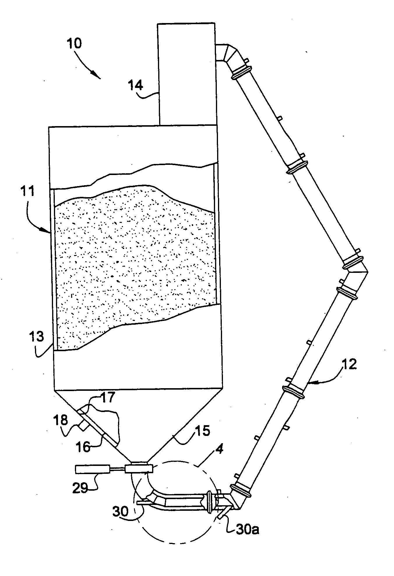
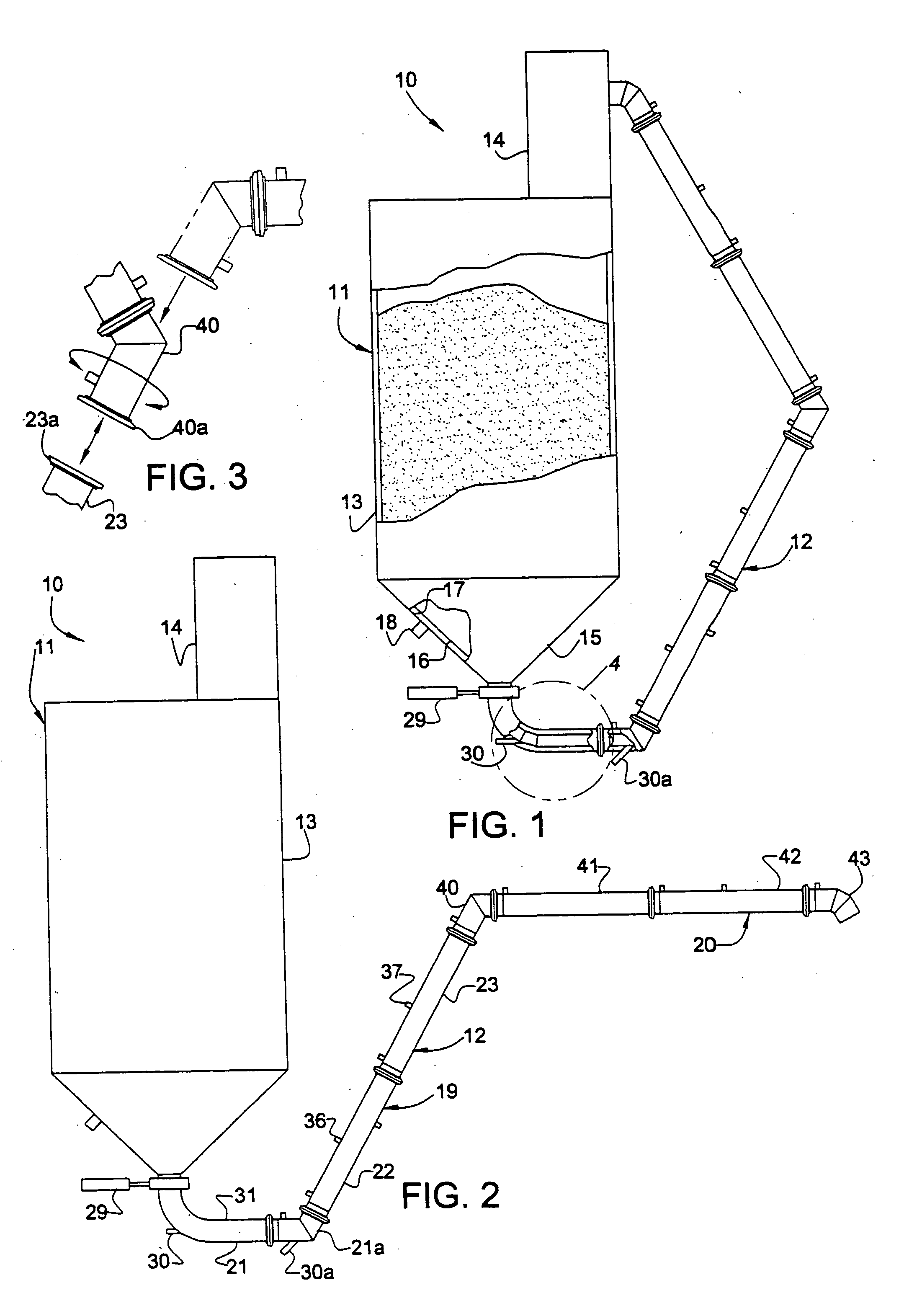
[0014] Referring to FIGS. 1 through 3 of the drawings, there is illustrated a system 10 embodying the present invention. Generally, the system includes a vessel 11 in which a bulk particulate material to be conveyed is stored, and a transport line 12. The vessel generally is of a conventional configuration including a cylindrical, main body section 13, an upper inlet section 14 and a lower outlet section 15. The lower, outlet section has an inverted, frusto-conical configuration with a discharge outlet at the lower end thereof. As best shown in FIG. 1, the interior of lower, outlet section 15 is provided with an inverted, frusto-conically configured wall member 16 formed of a gas permeable material and spaced from section 15 to provide a plenum 17 therebetween. Air under pressure is supplied to plenum 17 through an inlet 18, which is caused to flow through permeable wall member 16 to fluidize material deposited in lower section 15 of the vessel and thus enhance the flowability of th...


PUM


Abstract

A system for pneumatically conveying a bulk particulate material generally consisting of means for holding such material, having an inlet and an outlet; a first material transport line segment including a first conduit formed of a gas permeable material having an inlet communicating with the outlet of the holding means and an outlet, defining a material flow passageway, and a second conduit formed of a gas impermeable material spaced from and encompassing the first conduit, defining a plenum; a second material transport line segment including a first conduit formed of a gas permeable material having an inlet communicating with the outlet of the first conduit of the first segment, defining a continuation of the material flow passageway, and an outlet, and a second conduit section formed of a gas impermeable material spaced from and encompassing the first conduit thereof, defining a plenum; the second segment being displaceable relative to the first segment between a first position communicating the outlet of the first conduit of the second segment with a receptacle into which the material is to be conveyed, and a second position communicating the outlet of the first conduit of the second segment with the inlet of the material holding means; means for supplying gas under pressure to the plenums, causing such gas to penetrate the first conduits to fluidize material flowing in the passageways and means for inducing the flow of material in the passageways, causing material induced therein from the holding means to be impelled therethrough.

Description

[0001] This invention relates to a system for pneumatically conveying bulk particulate materials, and more particularly to such a system which may be operated to purge residual material remaining in the transport line thereof following a shutdown of the system. BACKGROUND OF THE INVENTION [0002] In a typical system for pneumatically conveying bulk particulate materials from a first site to a second site, there is provided a material feed receptacle located at the first site, a material receiving receptacle located at the second site, a transport line receiving material from the feed receptacle and guiding it to the receiving receptacle and means for injecting air under pressure into the transport line to impel the material fed therein. Such receptacles at either of such sites may consist of storage vessels, processing equipment and various other modes of transportation including truck bodies, railway cars and ship holds. [0003] Often, when the operation of such a system is shut down...

Claims


Application Information

Patent Timeline
Patent Type & Authority Applications(United States)
IPC IPC(8): B65G53/28B65G53/14B65G53/52B65G53/58
CPCB65G53/14B65G53/58B65G53/521B65G53/28
Inventor PFEIFFER, JOHN W.MOTHERSBAUGH, JAMES E.
Owner YOUNG INDS
Why Eureka
Try Eureka