Holder for disk drives

a technology for disk drives and holders, applied in the field of optical disk drives, can solve the problems of reducing affecting the restraining so as to improve the restraining force, reduce the squeezing force of the disk drive, and improve the chuck structure

Inactive Publication Date: 2006-01-19
SAMSUNG ELECTRO MECHANICS CO LTD
View PDF12 Cites 1 Cited by
  • Summary
  • Abstract
  • Description
  • Claims
  • Application Information

AI Technical Summary

Benefits of technology

[0014] The present invention has been made to solve the foregoing problems, and it is therefore an object of the present invention to provide a holder for disk drives having an improved structure of chucks and chuck supporting portions so that the chucks can perform downward circular motion along circular paths so as to reduce disk-seating force while enhancing restraining force against separation of a disk.

Problems solved by technology

That is, since the slim optical disk drive is mounted on a thin main body, the height of the disk drive itself is limited.
The enhanced seating force causes inconvenience to the user in using the disk drive, and thus the user applies excessive force to the disk holder thereby potentially damaging the disk drive and even the main body.
Then, the disk may be separated even under slight impact during high speed rotation so that the disk drive may not properly perform its function.
Further, in the case of a DVD for example having a double layer structure, an intermediate groove of the double layer structure may trap the chuck (i.e., half chucking) potentially causing problems to the seating process of the disk.

Method used


Image

  • Holder for disk drives
  • Holder for disk drives
  • Holder for disk drives

Examples


Embodiment Construction

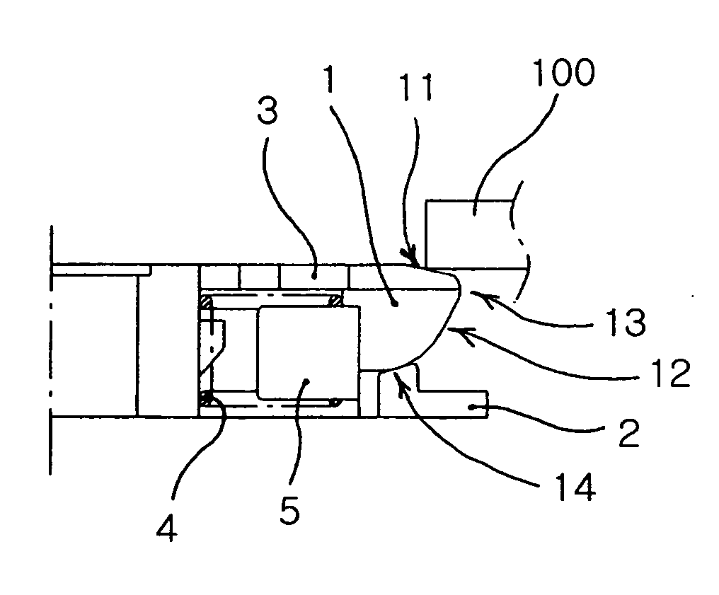
[0040] The following detailed description will present a preferred embodiment of the invention in reference to the accompanying drawings. FIG. 3 is a plan view of a holder for disk drives of the invention, and FIG. 4 is sectional view of a holder chuck in FIG. 3.

[0041] The disk holder of the invention comprises a hub 3, chucks 1 mounted on the hub 3 and supports 2 for supporting the chucks 1.

Holder Structure

[0042] The hub 3 has a generally circular sectional configuration, as shown in FIG. 3, to match an opening of a predetermined diameter formed in a central portion of a disk. The hub 3 is made of resin, and projected from an upper central portion of drive means including a stator assembly and a rotor assembly.

[0043] As shown in FIG. 4, each of the chucks 1 is mounted on the hub 3 so that the each chuck 1 can perform elastic motion in respect to the hub 3. The chuck 1 is elastically connected by its rear portion with the inside of the hub 3. That is, the rear portion of the ch...


PUM

PropertyMeasurementUnit
inclination angleaaaaaaaaaa
restraining forceaaaaaaaaaa

Abstract

The invention relates to an optical disk drive, and more particularly, to a holder for disk drives having an improved chuck structure for seating a disk. The holder of the invention, in use, is inserted into a central opening of a disk for detachably seating the disk, and comprises: a circular hub projected upward and sized equal to the central opening of the disk; a chuck projected from a lateral portion of the hub, wherein the chuck includes a rear portion elastically connected with the hub, a peak formed in a front portion of the chuck and a lower circular face of a curvature extended downward from the peak; and a support formed integral with the hub for contacting the lower circular face of the chuck to enable circular motion of the chuck.

Description

BACKGROUND OF THE INVENTION [0001] 1. Field of the Invention [0002] The invention relates to an optical disk drive, and more particularly, to a holder for disk drives having an improved chuck structure for seating a disk. [0003] 2. Description of the Related Art [0004] Optical disk drives, in particular, slim optical disk drives include a CD-ROM drive, a DVD-ROM drive, a CD R / W drive and so on. Such an optical disk drive receives a disk to write or read records into / from the disk while turning the disk. A slim optical disk drive is particularly mounted on a slim computer such as a notebook computer. [0005] The slim optical disk drive is limited in height. That is, since the slim optical disk drive is mounted on a thin main body, the height of the disk drive itself is limited. Therefore, the slim optical disk drive requires a holder structure for grasping a disk unlike a disk drive mounted on a typical desktop computer. [0006]FIG. 1 shows a conventional holder structure. As shown in ...

Claims


Application Information

Patent Timeline
Patent Type & Authority Applications(United States)
IPC IPC(8): G11B17/028G11B17/03G11B19/20
CPCG11B17/0282G11B17/028
Inventor KIM, TAE HEONCHOI, JUN KUNKIM, NAM SEOKKIM, JOON HOLEE, CHIL SUNG
Owner SAMSUNG ELECTRO MECHANICS CO LTD
Why Eureka
Try Eureka