Tool assembly for surgical stapling device

a tool assembly and surgical staple technology, applied in the direction of surgical staples, surgical forceps, paper/cardboard containers, etc., can solve the problems of time-consuming and inexact orientation of manipulations, and achieve the effect of convenient independent rotation of the tool assembly

Active Publication Date: 2006-01-26
TYCO HEALTHCARE GRP LP
View PDF99 Cites 352 Cited by
  • Summary
  • Abstract
  • Description
  • Claims
  • Application Information

AI Technical Summary

Benefits of technology

[0012] Preferably, the tool assembly is rotatably mounted to the collar member. In a preferred embodiment, the center rod of the coaxial cable is connected to the dynamic clamping device such that

Problems solved by technology

Such manipulations are time consuming and may not result in the

Method used


Image

  • Tool assembly for surgical stapling device
  • Tool assembly for surgical stapling device
  • Tool assembly for surgical stapling device

Examples


Embodiment Construction

[0034] Preferred embodiments of the presently disclosed surgical stapling device will now be described in detail with reference to the drawings in which like reference numerals designate identical or corresponding elements in each of the several views.

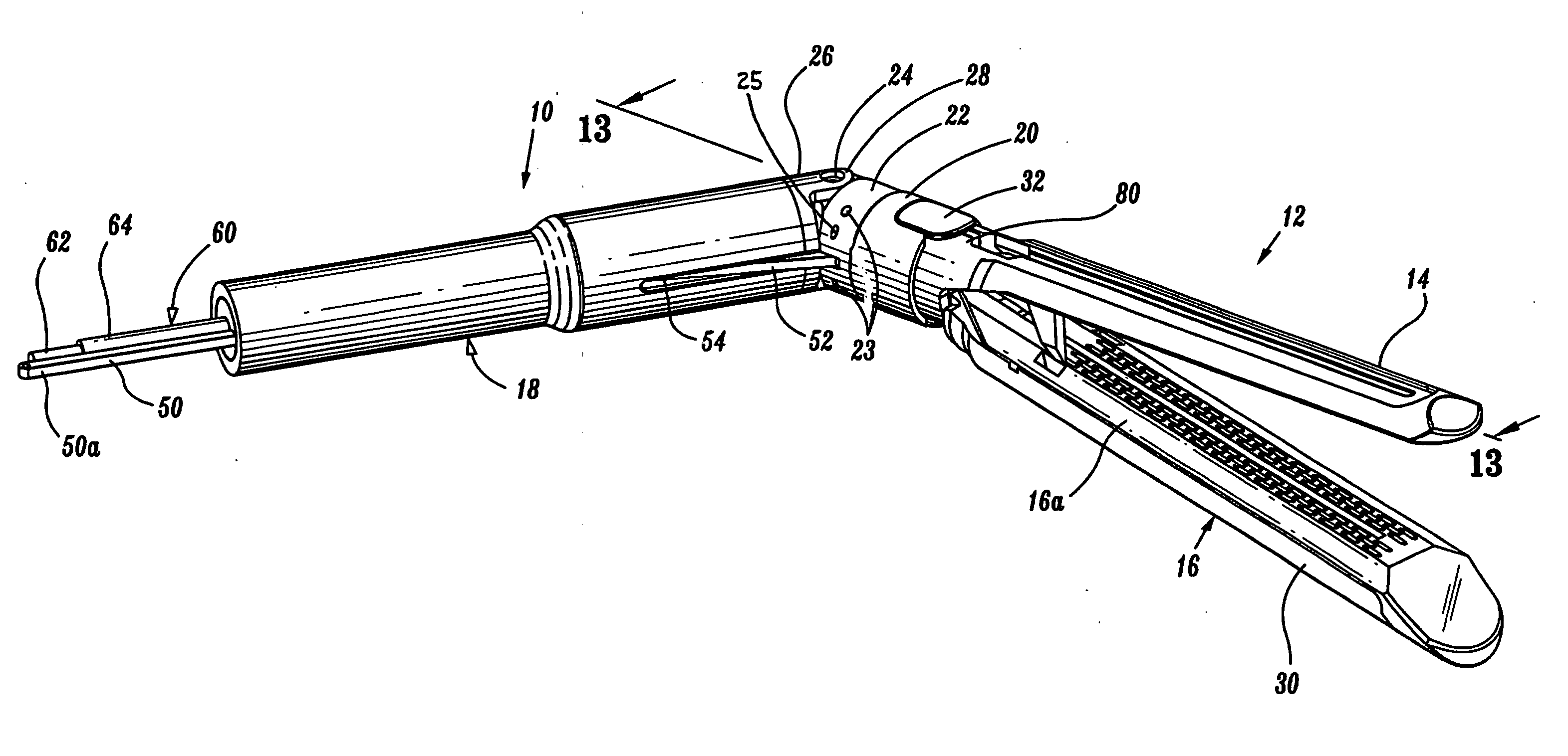
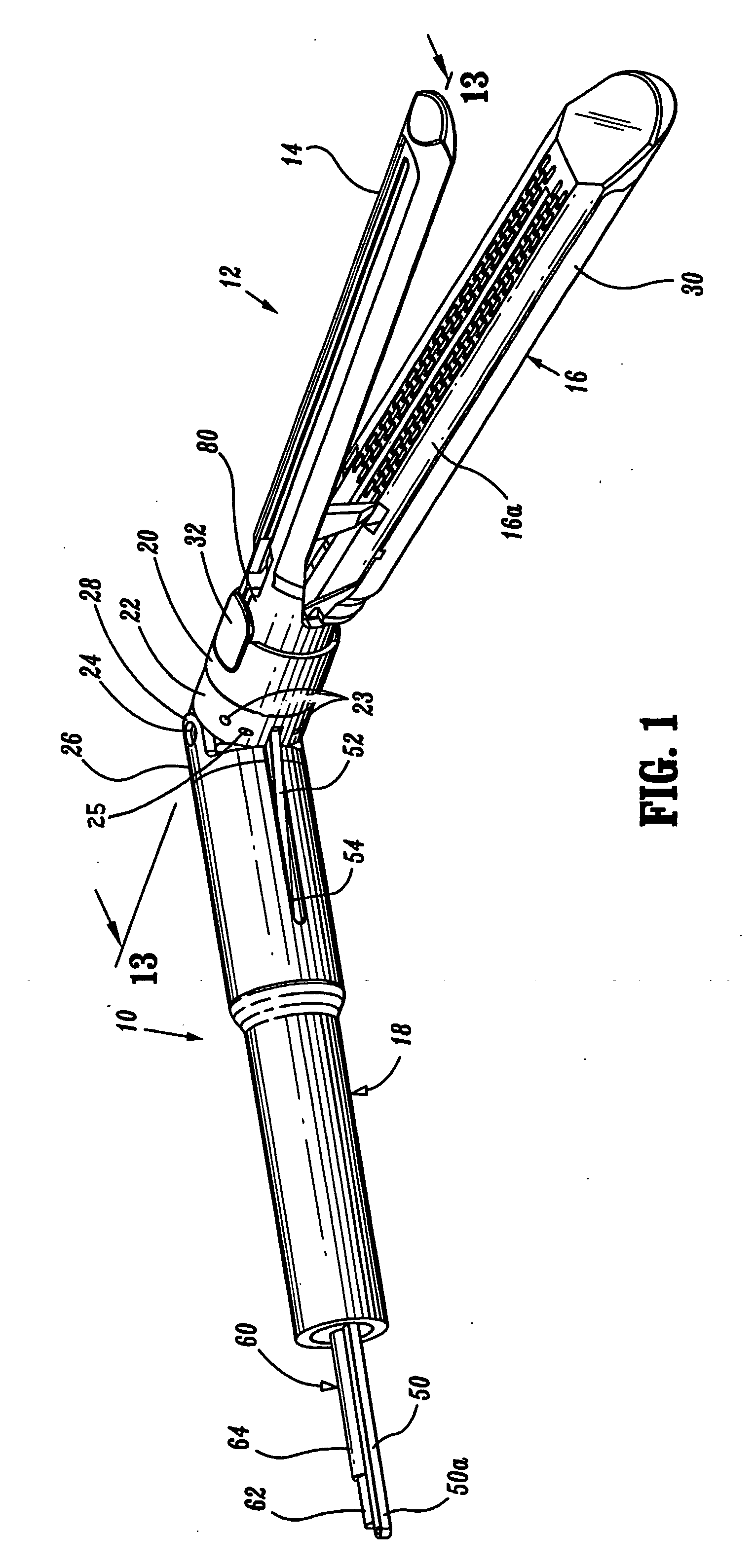
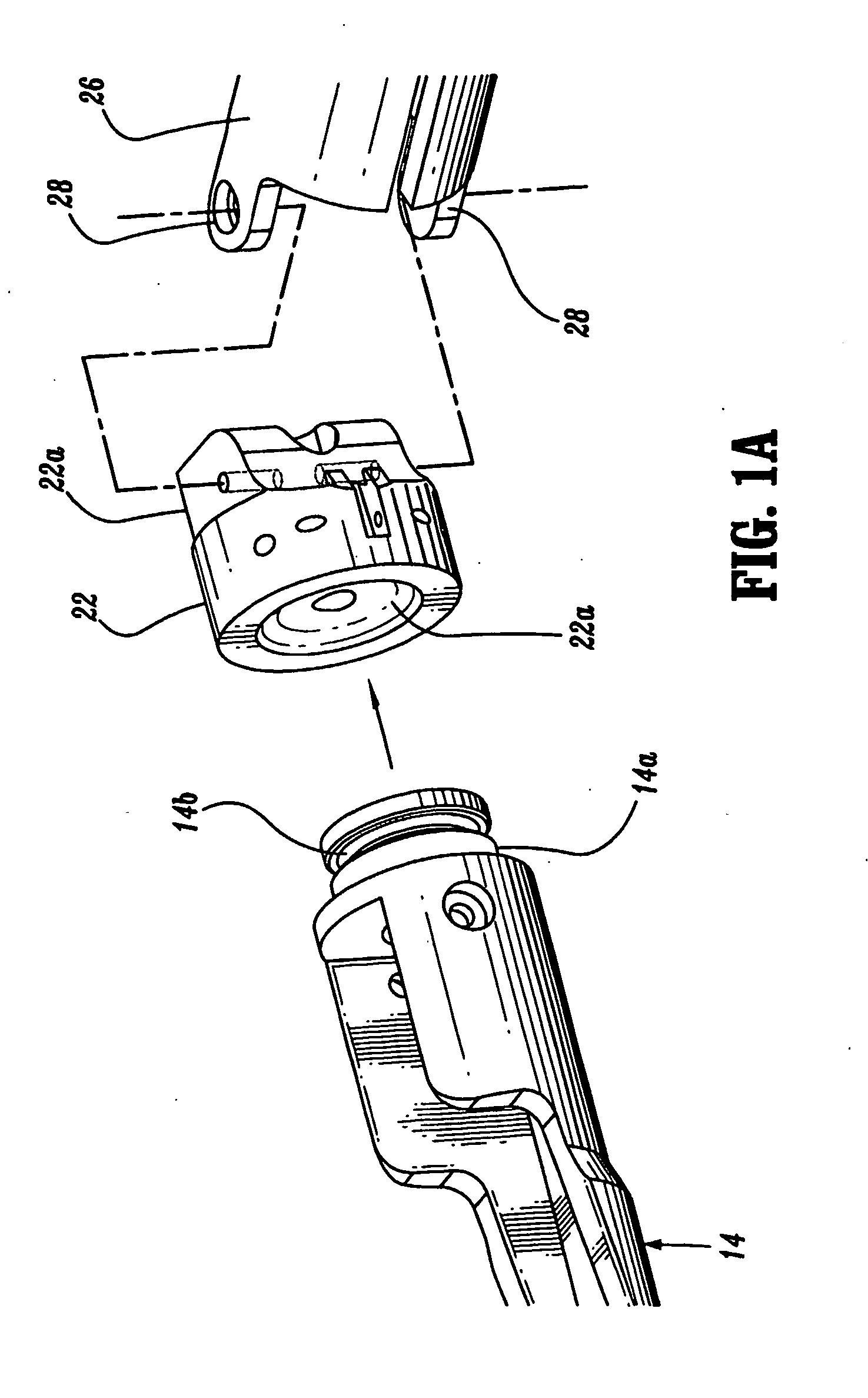
[0035]FIGS. 1-13 illustrate one preferred embodiment of the presently disclosed surgical stapling device shown generally as 10. Stapling device 10 includes a tool assembly 12 having an anvil 14 and a cartridge assembly 16, an endoscopic body portion 18, a clamp member 20, and a rotation collar 22. Tool assembly 12 is pivotally supported at the distal end of endoscopic body portion 18 about a pivot member 24. An adaptor 26 is secured to the distal end of body portion 18 and includes upper and lower extensions 28. A spacer 18a (FIG. 12) may be positioned within body anterior 8 to maintain the positioning of the internal components of the device. Alternately, adaptor 26 can be monolithically formed with endoscopic body portion 18. Pivot ...


PUM

PropertyMeasurementUnit
Flexibilityaaaaaaaaaa

Abstract

A surgical stapling device including an independently rotatable tool assembly is disclosed. The tool assembly includes an anvil and a cartridge assembly which are movable in relation to each other between spaced and approximated positions.

Description

[0001] This application claims priority from U.S. Provisional application Ser. No. 60 / 416,088, filed Nov. 4, 2002, entitled “Surgical Stapling Device”, which is incorporated herein in its entirety by reference.BACKGROUND [0002] 1. Technical Field [0003] The present disclosure relates to a tool assembly for treating tissue. More particularly, the present disclosure relates to an endoscopic surgical tool assembly capable of articulation and rotation for treating tissue. [0004] 2. Background of Related Art [0005] Surgical staplers for clamping tissue between opposed jaw structures of a tool assembly and thereafter fastening the clamped tissue are well known in the art. These devices may include a knife for incising the fastened tissue. Such staplers having laparoscopic or endoscopic configurations are also well known in the art. Examples of these endoscopic surgical staplers are described in U.S. Pat. Nos. 6,330,965, 6,250,532, 6,241,139, 6,109,500 and 6,079,606, all of which are incor...

Claims


Application Information

Patent Timeline
IPC IPC(8): A61B17/10A61B17/068A61B17/072A61B17/28
CPCA61B17/0686A61B17/07207A61B2017/003A61B2017/07214A61B2017/07278A61B17/068A61B2017/2926A61B2017/2927A61B2017/2929A61B2017/2939A61B2017/320052A61B2017/07285A61B17/105A61B2017/07257A61B2017/07271
Inventor RACENET, DAVIDC
Owner TYCO HEALTHCARE GRP LP
Why Eureka
Try Eureka