Drapery center transmission lug coupler

a transmission lug and coupler technology, applied in the field of window coverings, can solve the problems of difficult entry into the house, sag or go out, over-price, etc., and achieve the effect of facilitating the independent rotation of the drapery rod pair, facilitating the independent rotation of each drapery rod, and facilitating the rotation of adjacent drapery rods

Inactive Publication Date: 2020-05-07
CURRENT PROD CORP
View PDF0 Cites 5 Cited by
  • Summary
  • Abstract
  • Description
  • Claims
  • Application Information

AI Technical Summary

Benefits of technology

[0029]A coupler for a drapery rod system is presented that is configured to connect a pair of adjacent drapery rods and facilitate either independent rotation of the pair of drapery rods in one configuration while facilitating rotation in unison in another configuration. In one arrangement, the coupler includes a lug connected to a bracket positioned at the middle of the adjacent drapery rods. The lug includes an axle extending a length between opposing ends and includes a bearing housing connected to each side of the axle. In one configuration a drapery rod is connected to each end of the axle and its respective bearing housing, which facilitates independent rotation of each drapery rod. In another configuration, a coupler is connected to each side of the axle, outside of the bearing housing, which facilitates rotation of the adjacent drapery rods in unison. In this way, the coupler facilitates installation of adjacent drapery rods that may rotate independently or in unison.

Problems solved by technology

One problem associated with using a drapery rod system is when they are used to cover an elongated area, such as a bank of windows.
In these applications, using a single elongated drapery rod can be impracticable as long drapery rods can be difficult to ship, they can be difficult to get into a house, they can be difficult to fit in an elevator, they can sag or go out-of-round, they can be overly expensive, among other problems and challenges.
Alternatively, using multiple independent drapery systems can be undesirable as well.
This is because using multiple independent drapery rod systems can be expensive, as each independent drapery rod system has its own motor, control system, power source or power connection, brackets, among other redundant features.
In addition, using multiple independent drapery rod systems can pose control issues.
That is, the multiple independent drapery rod systems may not operate in unison with one another.
In addition, installing multiple independent drapery rod systems can pose problems.

Method used


Image

  • Drapery center transmission lug coupler
  • Drapery center transmission lug coupler
  • Drapery center transmission lug coupler

Examples


Embodiment Construction

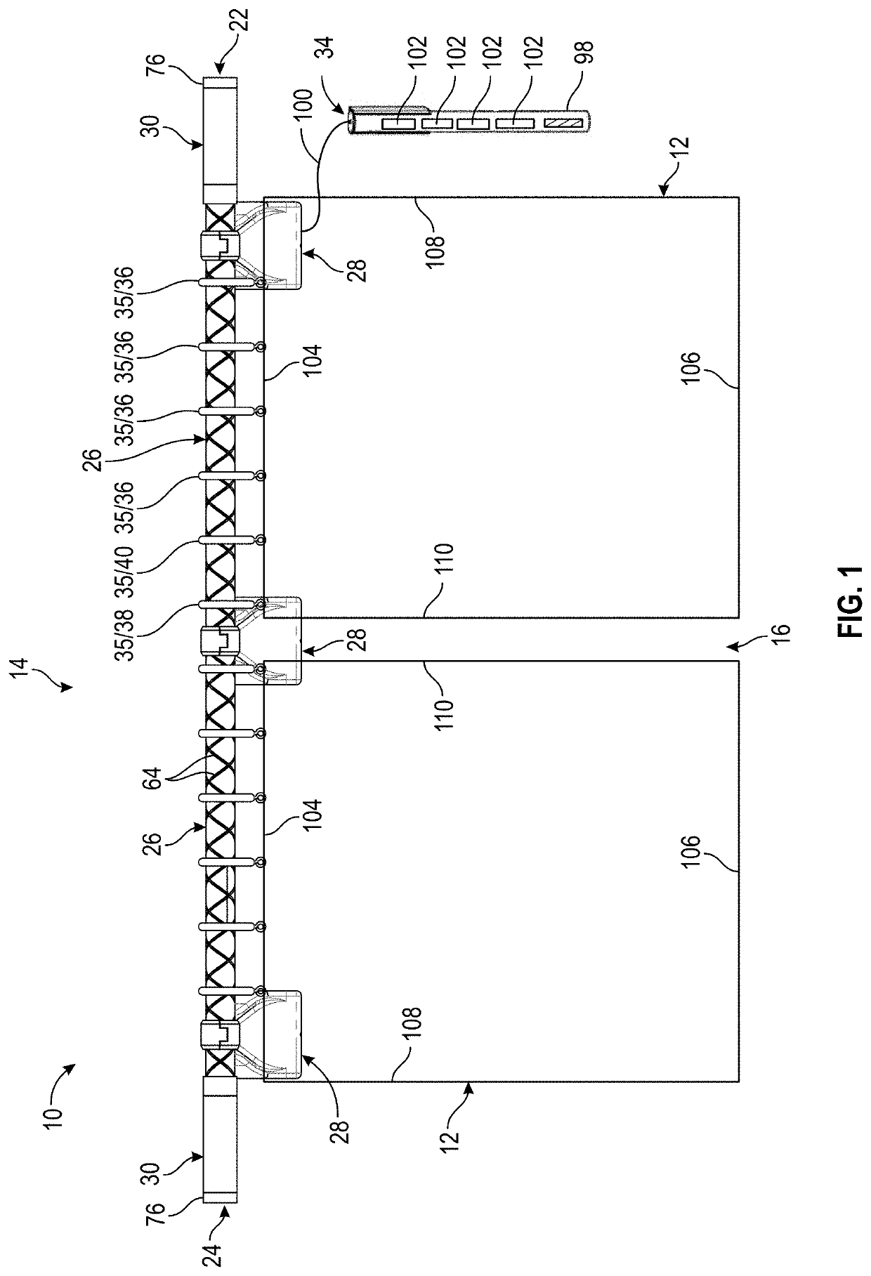
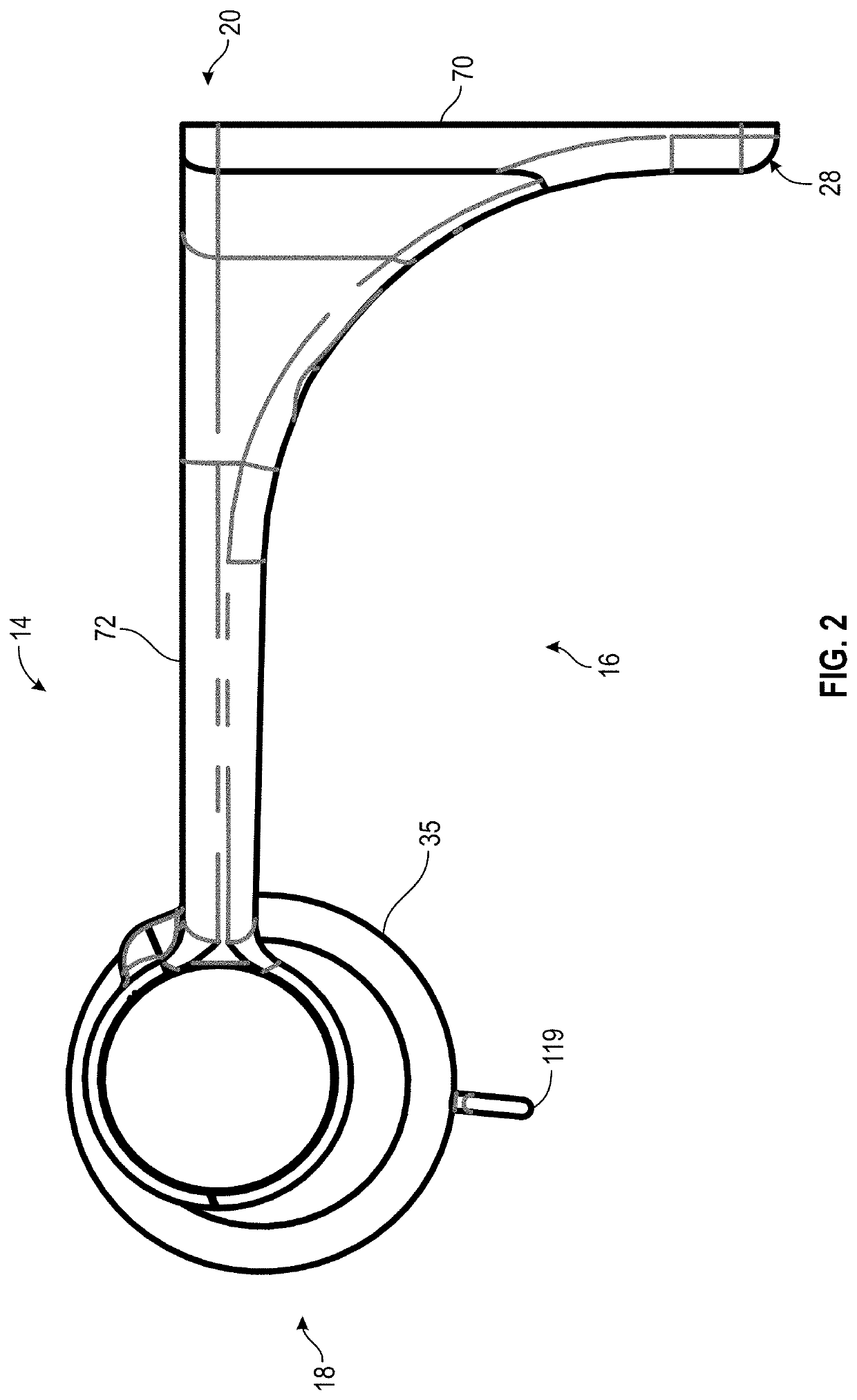
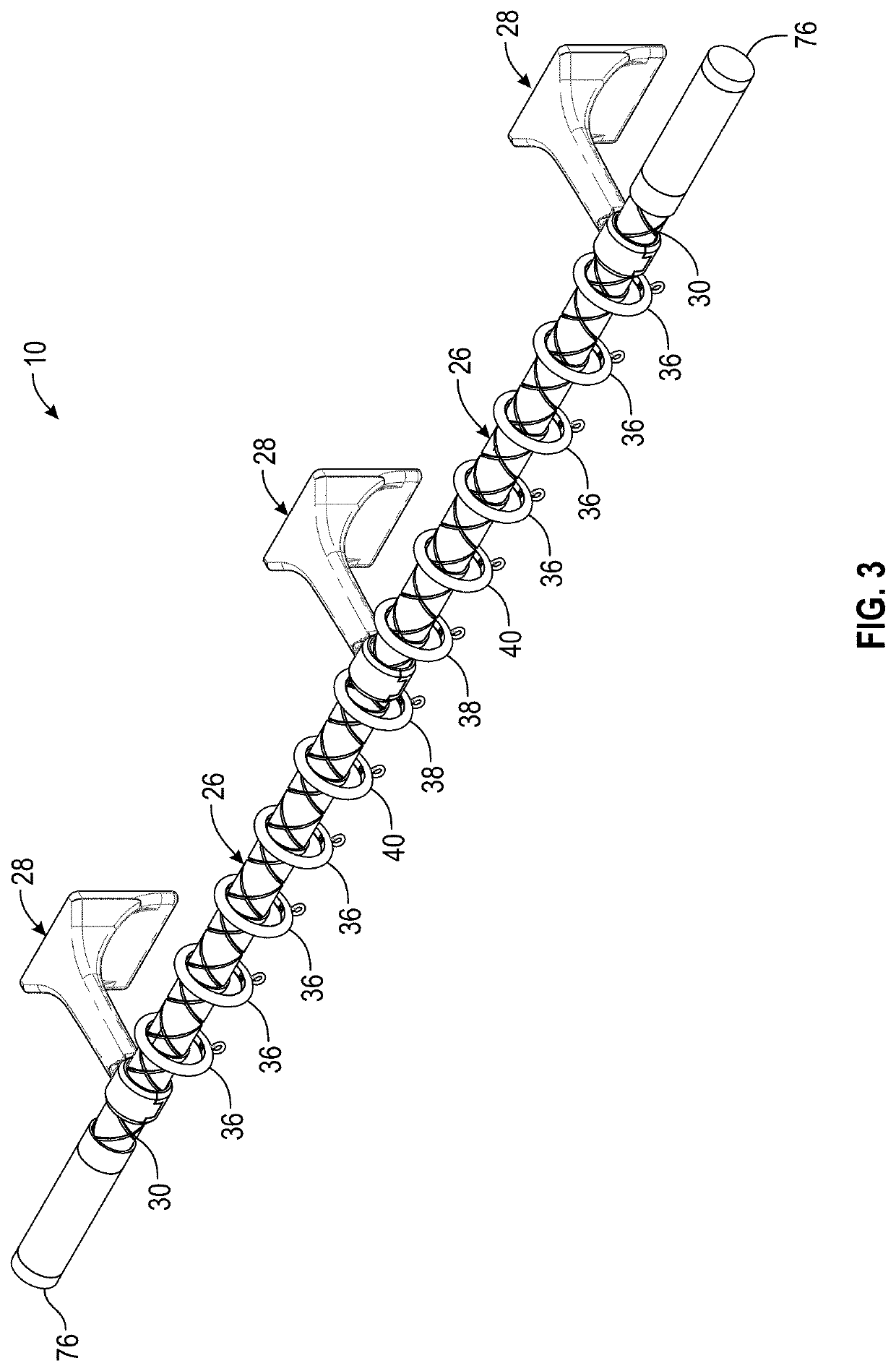
[0057]In the following detailed description, reference is made to the accompanying drawings which form a part hereof, and in which is shown by way of illustration specific embodiments in which the disclosure may be practiced. These embodiments are described in sufficient detail to enable those skilled in the art to practice the disclosure, and it is to be understood that other embodiments may be utilized and that mechanical, procedural, and other changes may be made without departing from the spirit and scope of the disclosure. The following detailed description is, therefore, not to be taken in a limiting sense, and the scope of the disclosure is defined only by the appended claims, along with the full scope of equivalents to which such claims are entitled.

[0058]As used herein, the terminology such as vertical, horizontal, top, bottom, front, back, end, sides, left, right, and the like are referenced according to the views, pieces, parts, components and figures presented. It should...


PUM


Abstract

A coupler for a drapery rod system that is configured to connect a pair of adjacent drapery rods and facilitate either independent rotation of the pair of rods in one configuration while facilitating rotation in unison in another configuration. In one arrangement, the coupler includes a lug connected to a bracket positioned at the middle of the adjacent drapery rods. The lug includes an axle extending a length between opposing ends and includes a bearing housing connected to each side of the axle. In one configuration a drapery rod is connected to each end of the axle and its respective bearing housing, which facilitates independent rotation of each rod. Another configuration, a coupler is connected to each side of axle, outside the bearing housing, which facilitates rotation of the adjacent rods in unison. In this way, the coupler facilitates installation of adjacent rods that may rotate independently or in unison.

Description

CROSS REFERENCE TO RELATED APPLICATIONS[0001]This application claims priority to U.S. Provisional Application No. 62 / 754,052 which was filed on Nov. 1, 2018, the entirety of which is incorporated herein fully by reference.FIELD OF THE DISCLOSURE[0002]This disclosure relates to window coverings. More specifically and without limitation, this disclosure relates to a rotating drapery rod system.BACKGROUND OF THE DISCLOSURE[0003]Architectural coverings, such as curtains, shades, draperies and the like are old and well known in the art and are frequently used to provide privacy and to limit the amount of light that is permitted to pass through a window and into a room or building. There are countless types, forms and designs of architectural coverings known in the art. The term architectural covering is used to describe any and all of these types, forms and designs including blinds, shades, draperies, and the like.[0004]One form of architectural covering of particular interest in this ap...

Claims


Application Information

Patent Timeline
Patent Type & Authority Applications(United States)
IPC IPC(8): A47H5/06A47H1/02
CPCA47H2001/0215A47H1/02A47H5/06A47H1/142
Inventor MULLET, WILLIS J.HAND, SCOTT
Owner CURRENT PROD CORP
Why Eureka
Try Eureka