Fiber optic probe tip

Active Publication Date: 2006-01-26
ONDINE INT
View PDF20 Cites 22 Cited by
  • Summary
  • Abstract
  • Description
  • Claims
  • Application Information

AI Technical Summary

Benefits of technology

[0008] In one embodiment, present invention is an improved fiber optic probe or probe tip. It includes an optical fiber that has an outside diameter that is suitable for insertion into a periodontal pocket or other kind of cavity or region within the human body. The optical fiber typically has a tapered end and a terminal or filler material, that is preferably made from a different material relative to the material that makes up the optical fiber, is typically connected to the tapered end of the fiber. In a preferred embodiment, the terminal material has an outer diame

Problems solved by technology

When activated by exposure to light, these drugs can cause cell necrosis.
While this type of design can disperse light laterally relative to the fiber, it suffers drawbacks in several respects.
It is obvious, therefore, that an enlarged probe tip is undesirable when used in applications of this type.
S

Method used


Image

  • Fiber optic probe tip
  • Fiber optic probe tip
  • Fiber optic probe tip

Examples


Example

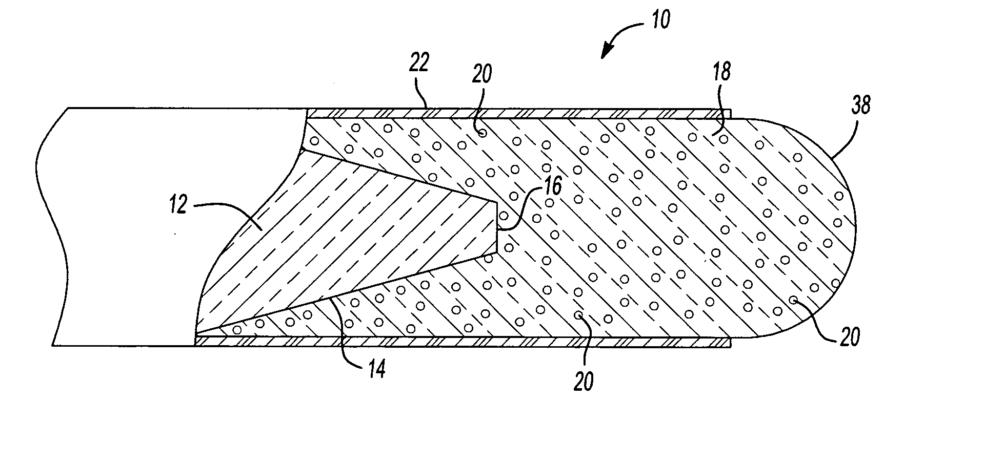
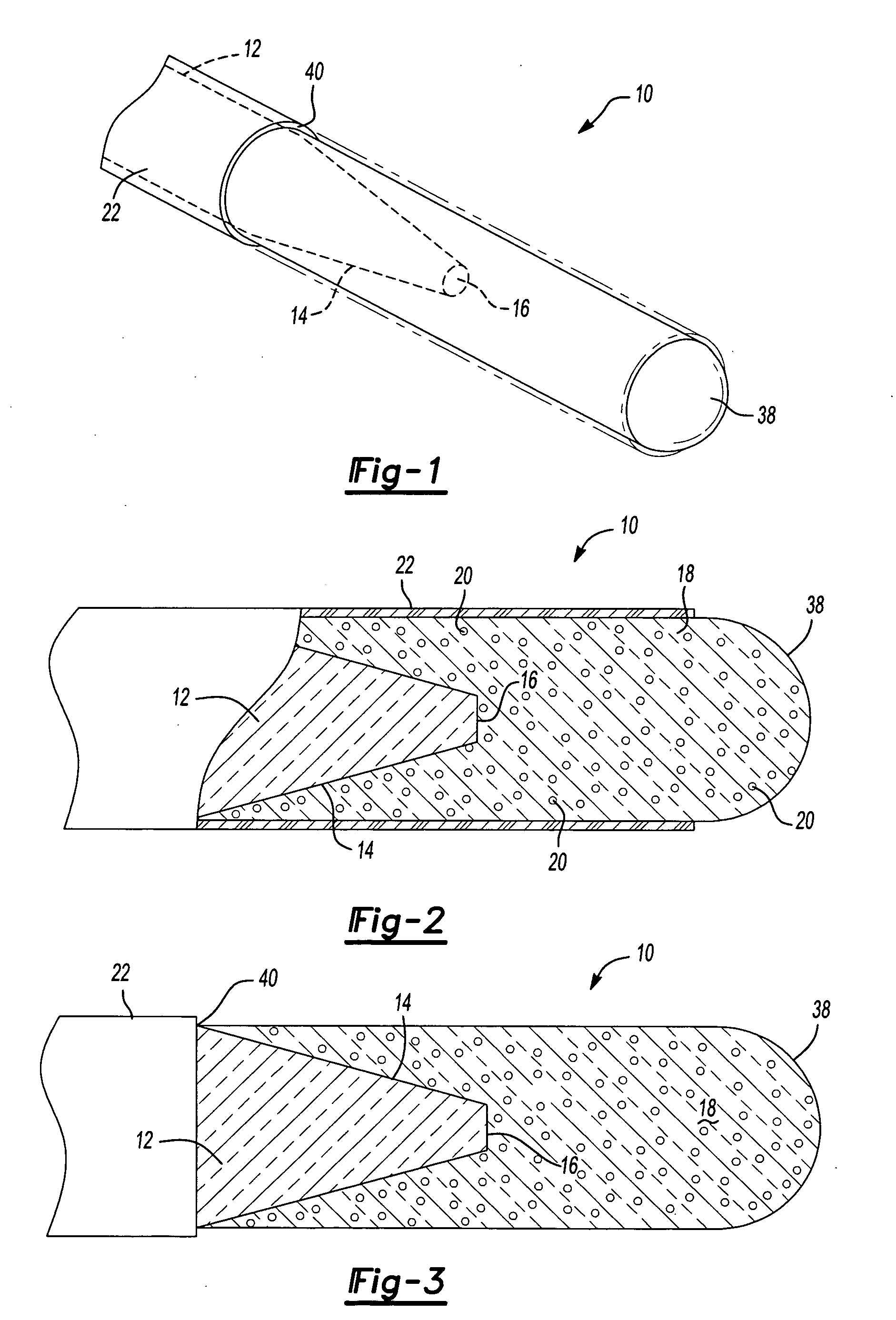
[0021] Referring now to FIG. 1, shown generally at 10 is a fiber optic probe or probe tip constructed in accordance with a preferred embodiment of the invention. The probe tip is constructed from an optical fiber 12 (e.g., a native, fused silica fiber optic cable). The end of the optical fiber 12 is tapered in the manner illustrated in the drawings. While the drawings illustrate a symmetrical, conical taper, with a truncated tip or face 16, it is to be appreciated that the taper may not follow a precise geometric configuration. The shape of the tapered end 14 may vary according to manufacturing techniques. For example, the tapered end 14 may be shaped as a full or partial wedge or may form any other shape that progressively reduces the cross-sectional area of the fiber 12 at the end.

[0022] The very end of the probe consists of a fill or terminal material 18, which is typically transparent or translucent, although not necessarily required for the entirety of the material. As shown i...


PUM

PropertyMeasurementUnit
Pressureaaaaaaaaaa
Diameteraaaaaaaaaa
Shapeaaaaaaaaaa

Abstract

The invention described here is an improved fiber optic probe. The tip of the probe is made from a transparent fill material that is connected to the end of a conventional optical fiber. The optical fiber is tapered, the fill material is connected thereto, and typically extends outwardly from the fiber as though it is a continuous part of the fiber. The outer diameter of the fill material is preferably essentially the same as the optical fiber. The fill material may contain light-scattering elements that disperse light as it exits the fiber.

Description

TECHNICAL FIELD [0001] The present invention generally relates to medical devices. More particularly, the invention relates to medical devices that deliver electromagnetic radiation to an area under treatment by means of an optical fiber. BACKGROUND OF THE INVENTION [0002] Photodynamic therapy (“PDT”) has been used to treat various maladies and diseases. PDT often involves the use of a photosensitizing agent that is activated by electromagnetic radiation (e.g., light such as laser light). Therapeutic treatments of this type have been known for many years. For example, in some instances they have been applied to the treatment of localized cancer. There are photosensitizing drugs such as hematoporphyrin derivatives that have selective application to tumors. When activated by exposure to light, these drugs can cause cell necrosis. An example of this type of treatment is disclosed in U.S. Pat. No. 4,336,809. [0003] PDT has also been used as a method for treating periodontal disease. Whe...

Claims


Application Information

Patent Timeline
IPC IPC(8): G02B6/26
CPCA61B18/22Y10T29/4902G02B6/262A61B2018/2261A61B2018/2244
Inventor LOEBEL, NICHOLAS
Owner ONDINE INT
Why Eureka
Try Eureka