System and method to effect the mitral valve annulus of a heart

a technology of mitral valve and annulus, which is applied in the field of system and method to effect the mitral valve annulus of a heart, can solve the problems of ineffective closure leakage through the mitral valve and regurgitation, and impaired normal functioning of the mitral valve in preventing regurgitation

Inactive Publication Date: 2006-01-26
CARDIAC DIMENSIONS
View PDF99 Cites 179 Cited by
  • Summary
  • Abstract
  • Description
  • Claims
  • Application Information

AI Technical Summary

Problems solved by technology

The normal functioning of the mitral valve in preventing regurgitation can be impaired by dilated cardiomyopathy caused by disease or certain natural defects.
This can result in deformation of the mitral valve geometry to cause ineffective closure of the mitral valve during left ventricular contraction.
Such ineffective closure results in leakage through the mitral valve and regurgitation.
Diseases such as bacterial inflammations of the heart or heart failure can cause the aforementioned distortion or dilation of the mitral valve annulus.
While the replacement of the entire valve eliminates the immediate problem associated with a dilated mitral valve annulus, presently available prosthetic heart valves do not possess the same durability as natural heart valves.
While the prior art methods mentioned above have been able to achieve some success in treating mitral regurgitation, they have not been without problems and potential adverse consequences.
Such procedures are expensive, are extremely invasive requiring considerable recovery time, and pose the concomitant mortality risks associated with such procedures.
Moreover, such open heart procedures are particularly stressful on patients with a compromised cardiac condition.
Further, the effectiveness of such procedures is difficult to assess during the procedure and may not be known until a much later time.
Hence, the ability to make adjustments to or changes in the prostheses to obtain optimum effectiveness is extremely limited.
For example, in the prior delivery system, described hereinbefore, release of the introducer from the device is difficult.
This action could cause the device position to change and adversarily alter its effectiveness.
Still further, neither the device nor the introducer were well suited for recapturing the device for removal.

Method used


Image

  • System and method to effect the mitral valve annulus of a heart
  • System and method to effect the mitral valve annulus of a heart
  • System and method to effect the mitral valve annulus of a heart

Examples


Embodiment Construction

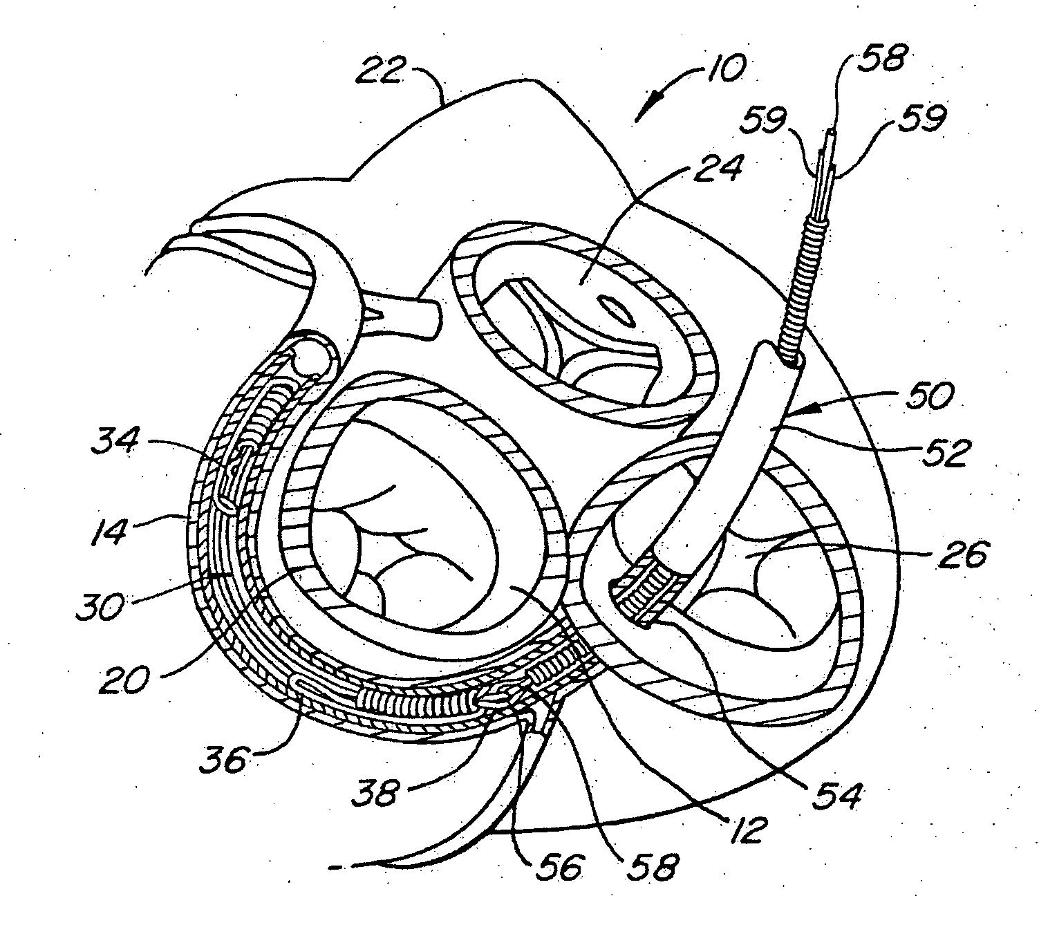
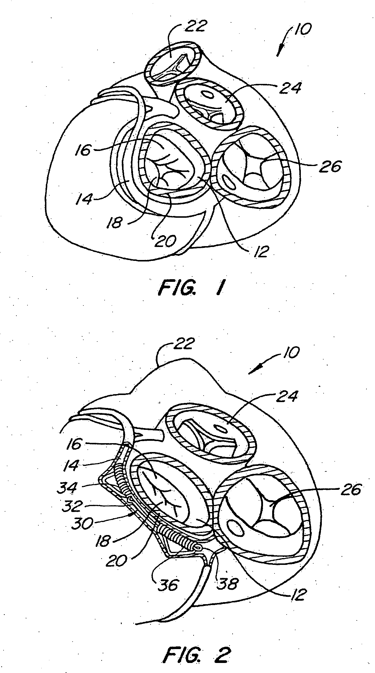
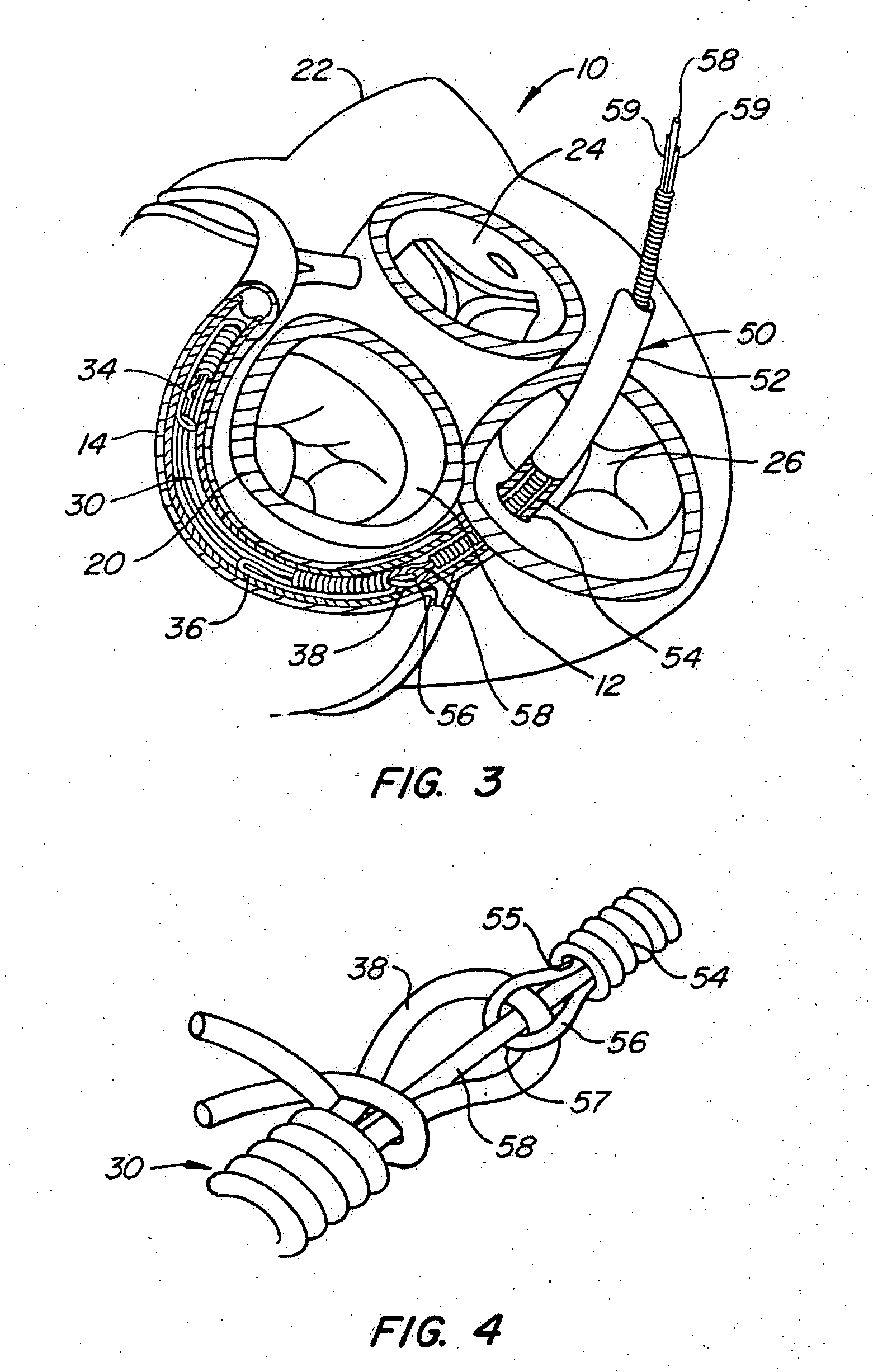
[0037] Referring now to FIG. 1, it is a superior view of a human heart 10 with the atria removed to expose the mitral valve 12, and the coronary sinus 14 of the heart 10. Also generally shown in FIG. 1 are the pulmonary valve 22, the aortic valve 24, and the tricuspid valve 26 of the heart 10.

[0038] The mitral valve 12 includes an anterior cusp 16, a posterior cusp 18 and an annulus 20. The annulus encircles the cusps 16 and 18 and maintains their spacing to provide a complete closure during a left ventricular contraction. As is well known, the coronary sinus 14 partially encircles the mitral valve 12 adjacent to the mitral valve annulus 20. As is also known, the coronary sinus is part of the venus system of the heart and extends along the AV groove between the left atrium and the left ventricle. This places the coronary sinus essentially within the same plane as the mitral valve annulus making the coronary sinus available for placement of the mitral valve therapy device of the pre...


PUM


Abstract

An assembly for effecting the condition of a mitral valve annulus includes a mitral valve therapy device, a coupling structure carried by the device, a catheter, a second coupling structure, and a locking member. To implant the device, the device is first releasably locked to a pushing member by the coupling structures and the locking member. When the device is positioned within the coronary sinus adjacent the mitral valve annulus and deployed, the coupling structures may be released from each other by the release of the locking member.

Description

CROSS-REFERENCES [0001] This application is a continuation application of Ser. No. 10 / 798,728, filed Mar. 10, 2004, which is a divisional application of Ser. No. 10 / 331,143, filed Dec. 26, 2002, which is incorporated herein by reference in its entirety, and to which application we claim priority under 35 U.S.C. § 121.FIELD OF THE INVENTION [0002] The present invention generally relates to a system and method to effect the mitral valve annulus of a heart. The present invention more particularly relates to a mitral valve annulus device, system, and method wherein the device is deployed and anchored in the coronary sinus of a heart adjacent the mitral valve annulus to reshape the mitral valve annulus. BACKGROUND OF THE INVENTION [0003] The human heart generally includes four valves. Of these valves, a most critical one is known as the mitral valve. The mitral valve is located in the left atrial ventricular opening between the left atrium and left ventricle. The mitral valve is intended...

Claims


Application Information

Patent Timeline
Patent Type & Authority Applications(United States)
IPC IPC(8): A61F2/24
CPCA61F2/2451
Inventor KOWALSKY, LEONARDNIEMINEN, GREGORY D.BRAXTAN, RYAN H.MATHIS, MARK L.
Owner CARDIAC DIMENSIONS
Why Eureka
Try Eureka