Devices and methods for coronary sinus pressure relief
a technology of coronary sinus and device, applied in the field of devices, can solve the problems of few, if any, proven effective treatments, increased end-diastolic pressure, symptom, morbidity and/or mortality, etc., and achieve the effects of reducing possible pressure necrosis, increasing flexibility without decreasing strength, and increasing radiopacity
- Summary
- Abstract
- Description
- Claims
- Application Information
AI Technical Summary
Benefits of technology
Problems solved by technology
Method used
Image
Examples
embodiment 200
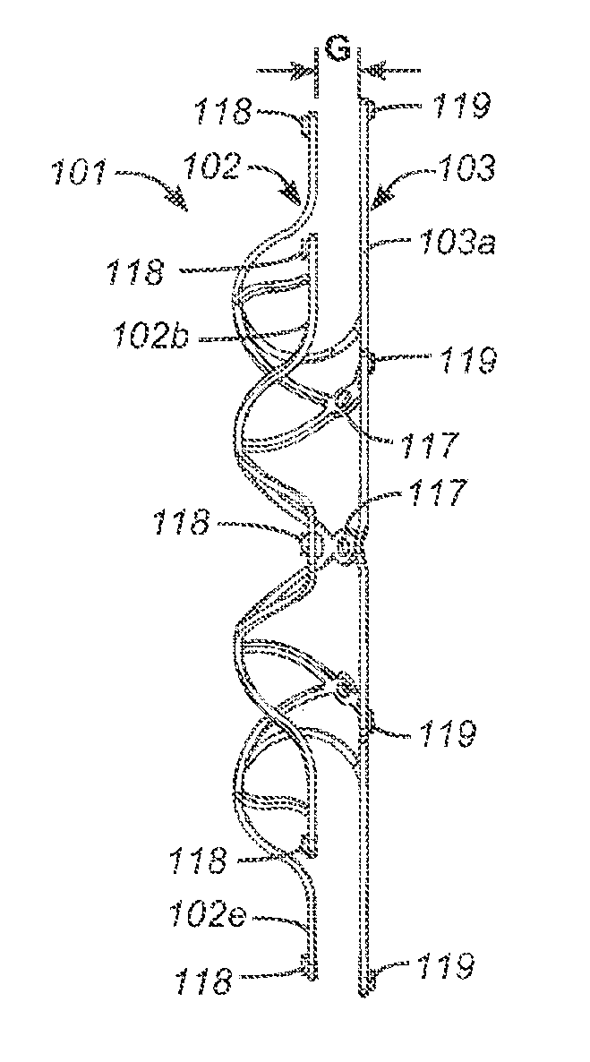
[0211]Referring now to FIG. 8, an interatrial pressure vent 100 is shown in its stowed configuration. In embodiments, the interatrial pressure vent can be collapsed to a substantially cylindrical shape for stowing in a delivery catheter during placement. Flange segments 102a-102h and 103a-103h can be fabricated to be substantially equal in length. The “stowed position” is not meant to apply only to devices having flange segments of equal length but rather to all embodiments of the venting device disclosed herein. Devices having flange segments of varying length and orientation such as those described herein are also designed to stow in substantially the same manner as shown in FIG. 8. In an embodiment 200 seen in FIG. 20, flange segments 202a-202h and 203a-203h are formed on a slanted angle so that, when marker elements are secured to the ends of the flange segments, the flange segments can be stowed into a smaller volume. In embodiments 300 seen in FIG. 21, flange segments 302a-302...
first embodiment
[0260]FIG. 31 depicts a mounting and loading tool useful for placing the prosthesis onto a catheter or other delivery device for delivery in vivo to a patient. In this embodiment, mounting tool 2001 includes a base plate 2002 with orifices 2003 for securing other components as shown with fasteners 2004 and pin 2009. The principal component is a loader body 2014, mounted via the outer two fasteners and orifices as shown. A mounting platform 2023 is mounted in the center of the loader body via the third orifice and pin 2009. Mounting platform 2023 includes a lower orifice 2026 for mounting to the loader body via the middle loader body orifice with pin 2009. Mounting platform 2023 also includes a slotted cam surface 2024. Pivot 2029 mounts to the loader body 2014 via pivot pin 2028 through pivot orifice 2030 and loader body orifice 2016. Pivot 2029 and lever 2031 mount on the left side of loader body 2014 below the side doors 2020, as seen in FIG. 31. Movement of pivot 2029 and lever 2...
third embodiment
[0350]a design for retrieval is depicted in FIGS. 48A and 48B. In this embodiment, prosthesis 151 is very similar to prosthesis 141 above, including retrieval sutures or wires 153 from bores 109 of the right atrium flange apices 102a-h, to a central annular retrieval suture or wire 157. Each retrieval suture or wire 153 is joined to the central retrieval thread 157 at a juncture 155. The junctures may simply be suture tie-offs; alternatively, the junctures could be orifices in central wire 157 for joining retrieval sutures or wires 153. In some embodiments, an additional retrieval suture or wire 147, suitable for non-invasive imaging, may be tied to the central thread at least at one point for grasping by a retrieval device.
[0351]A fourth embodiment of a prosthesis 161 designed for retrieval and redeployment is depicted in FIG. 49. Prosthesis 161 is similar to prosthesis 100a, described above. In the fourth embodiment, there is a retrieval wire or suture 163 secured to each apex 102...
PUM
 Abstract
Description
Claims
Application Information
 - R&D
- Intellectual Property
- Life Sciences
- Materials
- Tech Scout
- Unparalleled Data Quality
- Higher Quality Content
- 60% Fewer Hallucinations
Browse by: Latest US Patents, China's latest patents, Technical Efficacy Thesaurus, Application Domain, Technology Topic, Popular Technical Reports.
© 2025 PatSnap. All rights reserved.Legal|Privacy policy|Modern Slavery Act Transparency Statement|Sitemap|About US| Contact US: help@patsnap.com


