Complex Shaped Steerable Catheters and Methods for Making and Using Them

a catheter and complex technology, applied in the field of catheters, can solve the problems of difficulty in accessing the coronary sinus in patients undergoing such procedures, difficulty in and difficulty in obtaining the available devices, so as to promote the ease of understanding the position of the tip

Inactive Publication Date: 2007-01-18
INTUITIVE SURGICAL OPERATIONS INC
View PDF82 Cites 200 Cited by
  • Summary
  • Abstract
  • Description
  • Claims
  • Application Information

AI Technical Summary

Benefits of technology

[0010] In one embodiment, the bend may be defined by the left hand rule for helixes. For example, the direction of rotation of the distal portion may be represented by fingers of the left hand curving outward from the hand with the thumb defining, when extended from the hand, the general direction of propagation. Such a configuration may be particularly useful for cannulating the coronary sinus from a superior approach, i.e., when the right atrium is accessed from the superior vena cava. Specifically, a left handed helical deflection creates a direction vector at the tip of the device that matches the generally anatomically posterior entry vector of the coronary sinus ostium. Matching the tip vector with the entry vector facilitates much improved cannulation as compared to a simple tip curvature that may succeed in placing the tip of the device at the coronary sinus ostium but does not approach the sinus at a sufficiently ideal entry direction to facilitate cannulation. A left handed helical deflection is especially necessary when the location of the ostium relative to the entry plane of the device through superior vena cava exacerbates the mismatch of the entry vector of the sinus with the approach direction of a simple deflectable or shape set catheter.
[0011] In accordance with another embodiment, any of the apparatus described herein may include a transparent expandable member, e.g., a balloon or other membrane, on the distal end, and / or an imaging assembly including a distal lens, e.g., disposed proximal to or otherwise within the transparent expandable member. A bend, twist, or other deflection may be programmed into the distal portion proximal to the expandable member and / or the imaging system. The section of the tubular member extending beyond the bend may be generally straight and / or substantially rigid, e.g., which may maintain a view angle of an imaging lens of the imaging system substantially aligned with a distal face of the expandable member.
[0014] The corkscrew or other twisted portion of the distal portion may vary in length and / or location on the distal portion, depending on intended anatomical structures of a body cavity into which the apparatus is to be delivered. For example, if the apparatus approaches the right atrium of a heart from a superior position, the distal portion may be configured to move in a slight rightward inferior motion as it approaches the coronary sinus and then curve left in a posterior motion of deflection. This configuration may allow the tubular member to be manipulated through anatomical structures of a body cavity, e.g., through the right atrium into the coronary sinus.
[0018] In yet an alternative embodiment of the twisted and / or helical shape, the apparatus may be constructed such that the distal portion includes a twist, e.g., linear in pitch, such that deflection of a distal portion of the apparatus in at least one plane is substantially linear throughout most of the deflection of the distal portion. Alternatively, the steerable distal portion of the apparatus may deflect orthogonally to the direction of deflection in at least one plane such that the tip position defines a substantially linear pathway throughout most of the deflection. This configuration may allow the distal tip to be maintained within an open space of an atrium as it transitions from a straight undeflected configuration towards a desired complex curved configuration, e.g., for cannulating the coronary sinus or other body lumen, as described elsewhere herein.
[0019] In addition, this configuration may allow the apparatus to reach a desired shape without substantial interference with the boundaries of the atrium or body cavity. Second, the substantially linear tip deflection in at least one plane, may promote ease of understanding the position of the tip given the complex curve of the apparatus, e.g., while monitoring the apparatus using a two-dimensional imaging or reference system, such as fluoroscopy or other x-ray system.

Problems solved by technology

Taken together, these variations make transvenous coronary sinus access challenging, e.g., to deliver a catheter, lead, or other device into the coronary sinus.
Patients undergoing such procedures may suffer hardship given available devices, e.g., because of the delay or other difficulty in accessing the coronary sinus.
In some situations, because such access may be monitored tactilely or using two-dimensional imaging, such as fluoroscopy, a physician may be unable to access the coronary sinus in some anatomy.

Method used


Image

  • Complex Shaped Steerable Catheters and Methods for Making and Using Them
  • Complex Shaped Steerable Catheters and Methods for Making and Using Them
  • Complex Shaped Steerable Catheters and Methods for Making and Using Them

Examples


first embodiment

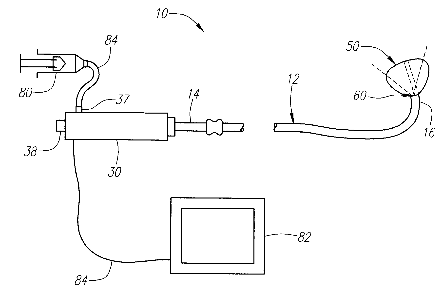
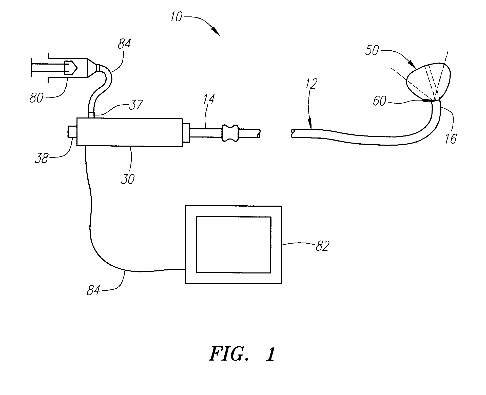
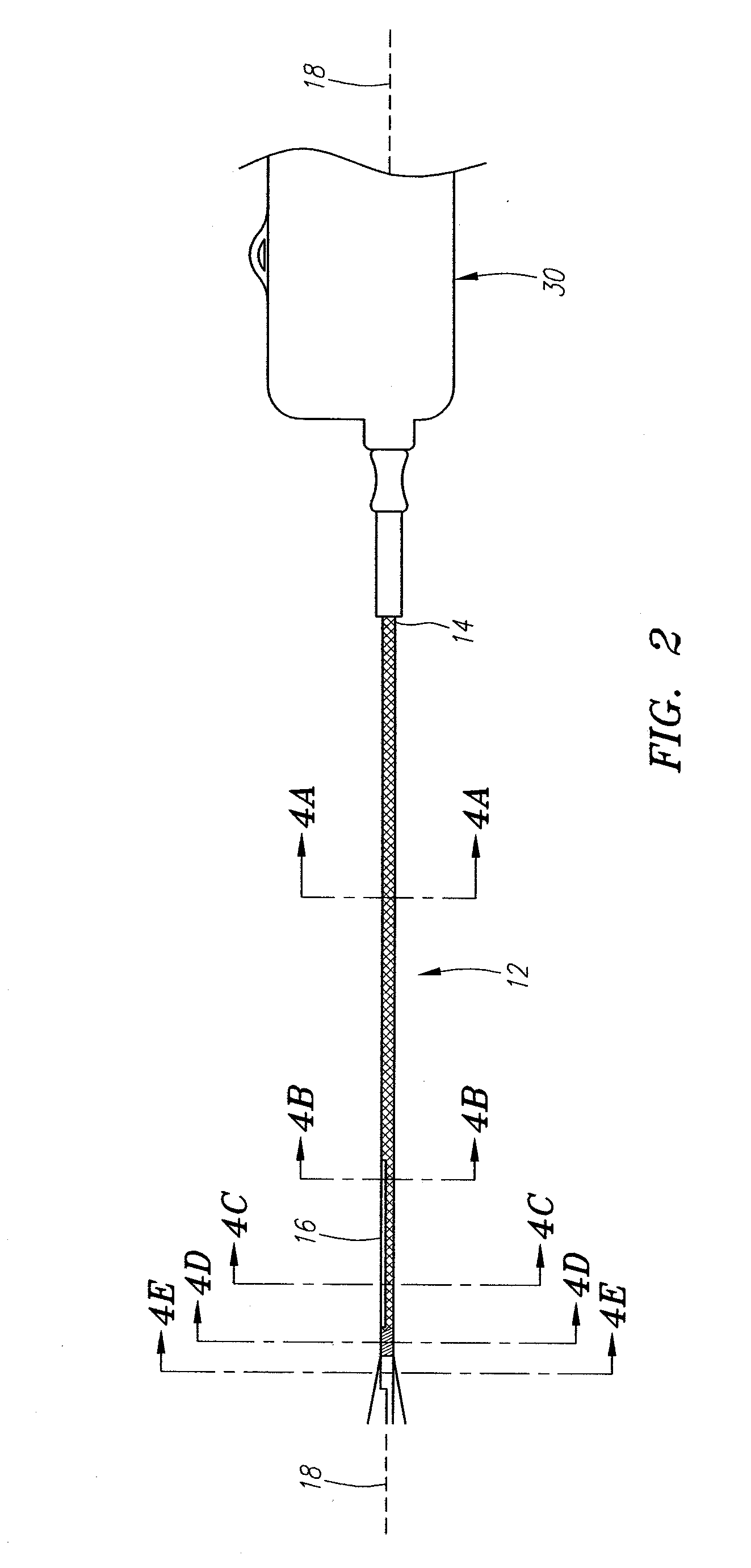
[0053] Turning to the drawings, FIGS. 1-3 show an apparatus 10 for imaging a body lumen, e.g., for visualizing, cannulating, and / or accessing a body lumen from a body cavity (not shown). As explained further below, the apparatus 10 may be used for imaging a wall of a body lumen, e.g., a right atrium of a heart, e.g., for visualizing, accessing, and / or cannulating a coronary sinus ostium. Alternatively, the apparatus 10 may be used for visualizing, accessing, and / or cannulating other body lumens, e.g., for delivering one or more therapeutic and / or diagnostic agents into tissue, and / or for puncturing through tissue to access a region beyond the punctured tissue. As used herein, “body lumen” may refer to any passage within a patient's body, e.g., an artery, vein, or other blood vessel, or a body cavity, such as a chamber within a patient's heart, e.g., a ventricle or atrium. Although exemplary embodiments are described herein, additional information that may relate to the structure and...

second embodiment

[0077] Turning to FIGS. 11-14, a distal end 216 of a catheter 212 is shown, which may be constructed generally similar to the previous embodiments described herein. FIG. 11 shows the distal end 216 in a substantially straight, relaxed configuration. In FIGS. 12 and 13, the distal end 216 has assumed a complex curved configuration, e.g., upon actuation of a steering mechanism (not shown). The complex curved configuration may include a gradual curved portion 216a that extends out of a plane, and a twisted portion 216b distal to the gradual curved portion 216a. As best seen in FIG. 13, the twisted portion 216b may resemble a portion of a corkscrew or helical shape, while the gradual curved portion 216a may have a generally “J” shape. Thus, the distal end 216 may resemble a corkscrew or helical twist in the complex curved configuration that may allow the catheter 212 to extend through varying geometrical shapes of anatomy, e.g., through a patient's right atrium into a coronary sinus. Op...

third embodiment

[0079] Referring to FIG. 15-19, a third embodiment is shown of a catheter 212 that generally includes a proximal end (not shown) and distal end 316 sized for introduction into a body lumen, similar to the previous embodiments. The distal end 316 is shown in a relaxed configuration in FIGS. 15 and 16, and in a complex curved configuration in FIGS. 17 and 18. In the relaxed configuration, the distal end 316 includes a slightly curved shape in two planes, as shown in FIGS. 15 and 16. In the complex curved configuration, the distal end 316 assumes a curvilinear shape, including a first gradual curve 316a within a first plane, and a second smaller curve 316b within a single plane that intersects the first plane. FIG. 19 shows the distal end 316 in another complex curved configuration created by actuating an internal steering adjustment member, as described elsewhere herein.

[0080] Optionally, any of the embodiments described herein may include a substantially transparent expandable member...


PUM


Abstract

Apparatus and methods are provided for accessing a body lumen within a patient's body. Generally, the apparatus includes a tubular member including proximal and distal ends, a steering element extending between the proximal and distal ends, and an actuator for directing the distal end between a relaxed configuration and a complex curved configuration. In the relaxed configuration, the distal end may assume a straight or curved shape. In the complex curved configuration, the distal end may assume a curvilinear shape. In one embodiment, the complex curved configuration may include a first curved portion defining an arc within a plane, and a second portion that extends out of the plane. An embodiment with a left hand rule configuration may be introduced into the right atrium of a heart from a superior approach, and the complex curved configuration may facilitate accessing the coronary sinus.

Description

[0001] This application claims benefit of provisional application Ser. Nos. 60 / 678,517, filed May 6, 2005 and Ser. No. 60 / 752,763, filed Dec. 20, 2005. The entire disclosures of these applications are expressly incorporated herein by reference.FIELD OF THE INVENTION [0002] The present invention relates generally to catheters for introduction into body lumens within a patient's body, and, more particularly, to complexly shaped catheters for accessing body lumens, cavities, and / or visualization within a patient's body and to methods for constructing and using such catheters. BACKGROUND [0003] Minimally invasive procedures have been implemented in a variety of medical settings, e.g., for vascular interventions, such as angioplasty, stenting, embolic protection, electrical heart stimulation, heart mapping and visualization, tissue ablation, and the like. One such procedure involves delivering an electrical lead into a coronary vein of a patient's heart that may be used to electrically s...

Claims


Application Information

Patent Timeline
Patent Type & Authority Applications(United States)
IPC IPC(8): A61M31/00A61B1/06
CPCA61B1/00165A61M25/0023A61M25/0032A61M25/005A61M2025/0161A61M25/0147A61M25/10A61M2025/0036A61M25/0105
Inventor LEEFLANG, STEPHEN A.MORRISON, GEORGE A.MOURLAS, NICHOLAS J.EVERSULL, CHRISTIAN S.
Owner INTUITIVE SURGICAL OPERATIONS INC
Why Eureka
Try Eureka