
Arterial cannula for cardiac surgery

Inactive Publication Date: 2014-07-17
GLAUBER MATTIA
View PDF4 Cites 1 Cited by
  • Summary
  • Abstract
  • Description
  • Claims
  • Application Information

AI Technical Summary

Benefits of technology

The cannula described in this patent is designed to make it safer and easier to insert a catheter into a patient's aorta, which is a significant improvement over current methods. The use of a pledget and a mechanical stopper to prevent excessive bleeding and a pledget to guide and hold the catheter in place are new and innovative techniques that enhance the surgeon's ease of use and patient safety.

Problems solved by technology

The ability to see into the operating field is often quite limited, meaning that the instruments for this type of procedure are specialized.
Currently cannulae are not sufficiently automated for these more minimally invasive surgical procedures, because the cardiac surgeon must hold and manipulate the cannula with one hand during aortic cannulation, the other hand is often used to open the incision area, hold the tourniquet and purse strings while the cannula is being inserted into a position somewhat blind and often too far to the surgeon.
For this reason, a single position retractable blade on the introducer as described in U.S. Pat. No. 6,488,693 allow the cut and insertion of the cannula as an automated self retracting blade system; the major shortfall with this approach is that one does not know for sure if the blade has been extended or not, which poses a substantial risk in piercing the opposite wall of the vessel being cannulated.
First hand experience with the commercially available device described in this patent also indicates that it is not so uneasy to push the blade too far into the cannula, dissecting the wall opposite of the cannulation site, which poses a significant risk to the patient's safety.
This second cut or hole must be repaired prior to moving on with the surgical procedure, and getting to the distal cut is not particularly an easy task in a mini thoracotomy approach; this can also lead to conversion to a full sternotomy, which is what is trying to be avoided in the first place.
There is also a need to help the guide of the cannula into place since visualization of the cannulation site is problematic in these minimally invasive procedures.

Method used


Image

  • Arterial cannula for cardiac surgery
  • Arterial cannula for cardiac surgery
  • Arterial cannula for cardiac surgery

Examples


Embodiment Construction

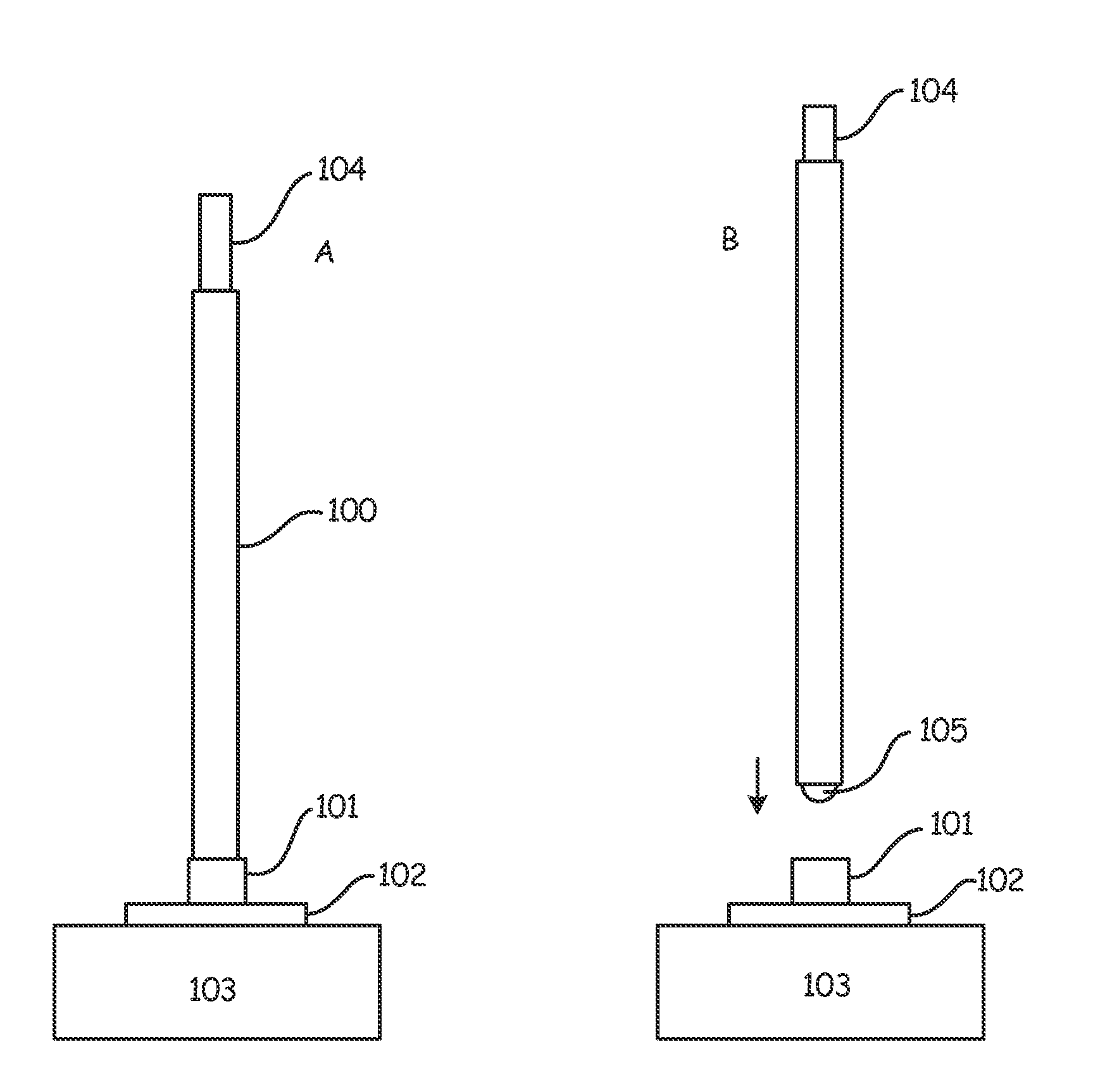
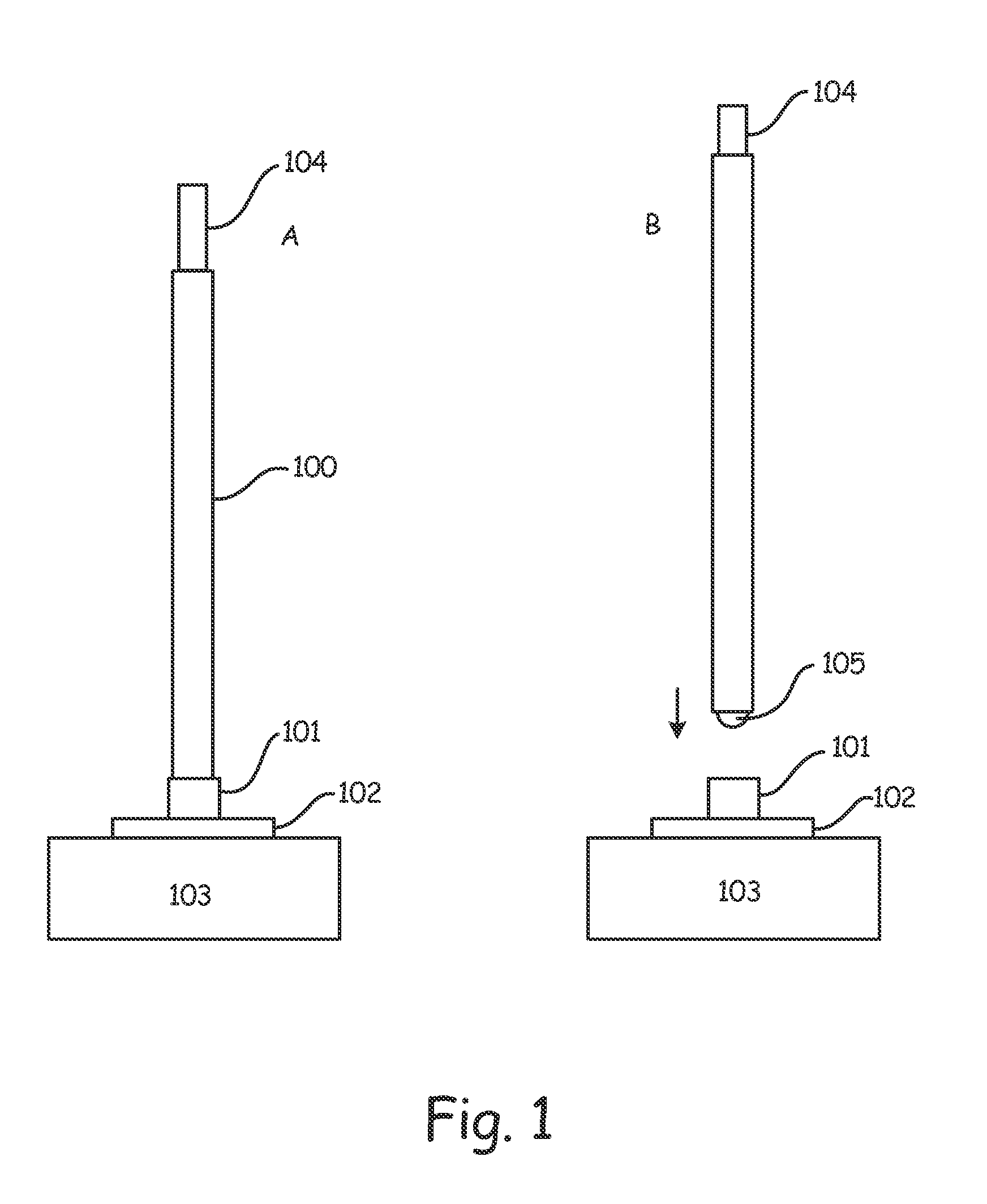
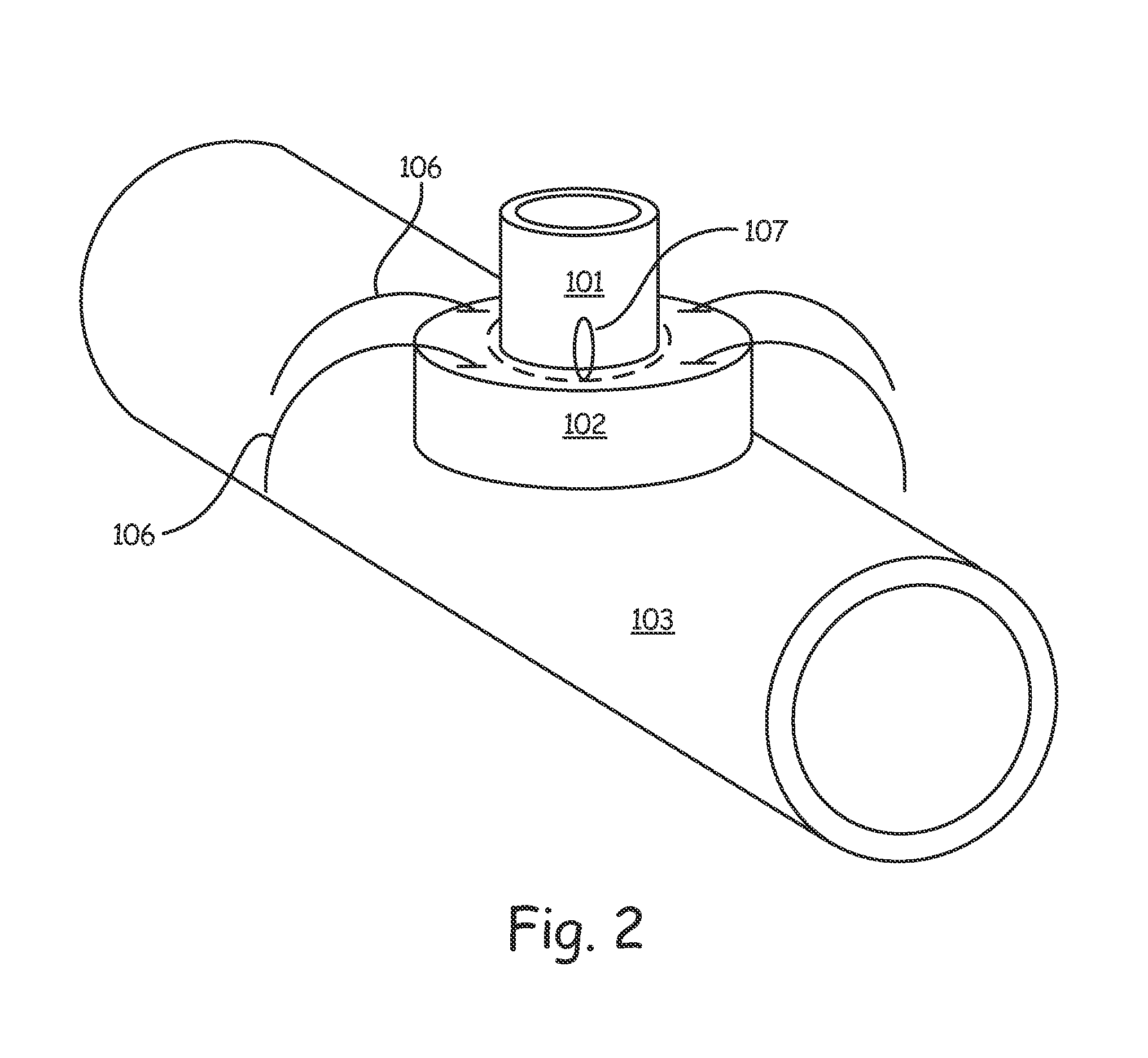
[0018]The cannula according to the invention includes three separate components, the cannula body (100), the pledget and stopper assembly (101 / 102), and the introducer (104).

[0019]The cannula shape and its dimensions are preferably according to those already known in the art.

[0020]The introducer (104) is a semi rigid tube placed coaxially inside the cannula to facilitate cannula placement and can include a hole for wire introducer commonly used to guide the introducer and cannula assembly to the required location. The introducer can be made from a semi-rigid material such as a polyolephin or other plastic that will assist in guiding the cannula assembly to the designated cannulation site. Specific to this embodiment, the introducer includes a sharp end that protrudes past the cannula tip, either the material itself being sharp enough to piece the vessel at the cannulation site or a small blade 1 to 3 mm in depth could be included in the introducer tip to permit simple and easy vesse...


PUM


Abstract

An arterial cannula for cardiac surgery includes a pledget / stopper assembly and an introducer. The pledget / stopper assembly is mechanically mated with an external surface of the cannula in proximity to its tip. The introducer has suitable dimension for being placed coaxially inside the cannula. The introducer has at its end a blade or a sharp edge that protrudes the cannula tip no more than 5 mm.

Description

CROSS-REFERENCE TO RELATED APPLICATIONS[0001]This application is a national phase application of PCT Application No. PCT / EP2012 / 060715, internationally filed Jun. 6, 2012, which claims priority to Italian Application No. FI2011A000116, filed Jun. 7, 2011, both of which are herein incorporated by reference in their entirety.TECHNICAL FIELD[0002]The present invention refers to the field of surgery devices and in particular to an arterial cannula for cardiac surgery, particularly suitable for mini-invasive cardiac surgery.BACKGROUND[0003]Cardiac surgery includes the need to provide some sort of extracorporeal circulation where the blood is oxygenated as the cardiac surgeon makes surgical corrections to the patient's still heart. The state of the art has evolved to a more “minimally invasive” approach which is based on trying to reduce the size of the surgical incision made in the patient's chest from a fully opened chest at the sternum (full sternotomy) to an approach that results in a...

Claims


Application Information

Patent Timeline
IPC IPC(8): A61B17/34
CPCA61B17/3415A61B2017/00243A61B2017/3425A61B2017/3488A61M2210/127
Inventor GLAUBER, MATTIA
Owner GLAUBER MATTIA
Learn More