
Bottom drawer type refrigerator having basket lift device

Inactive Publication Date: 2006-02-02
LG ELECTRONICS INC
View PDF20 Cites 60 Cited by
  • Summary
  • Abstract
  • Description
  • Claims
  • Application Information

AI Technical Summary

Benefits of technology

[0011] Therefore, an object of the present invention is to provide a bottom drawer type refrigerator having a basket lift device capable of enhancing users' convenience by lifting a position of the basket in such a manner that when a basket disposed at a lower portion of a main body of the refrigerator is drawn out, it is lifted upwardly.

Problems solved by technology

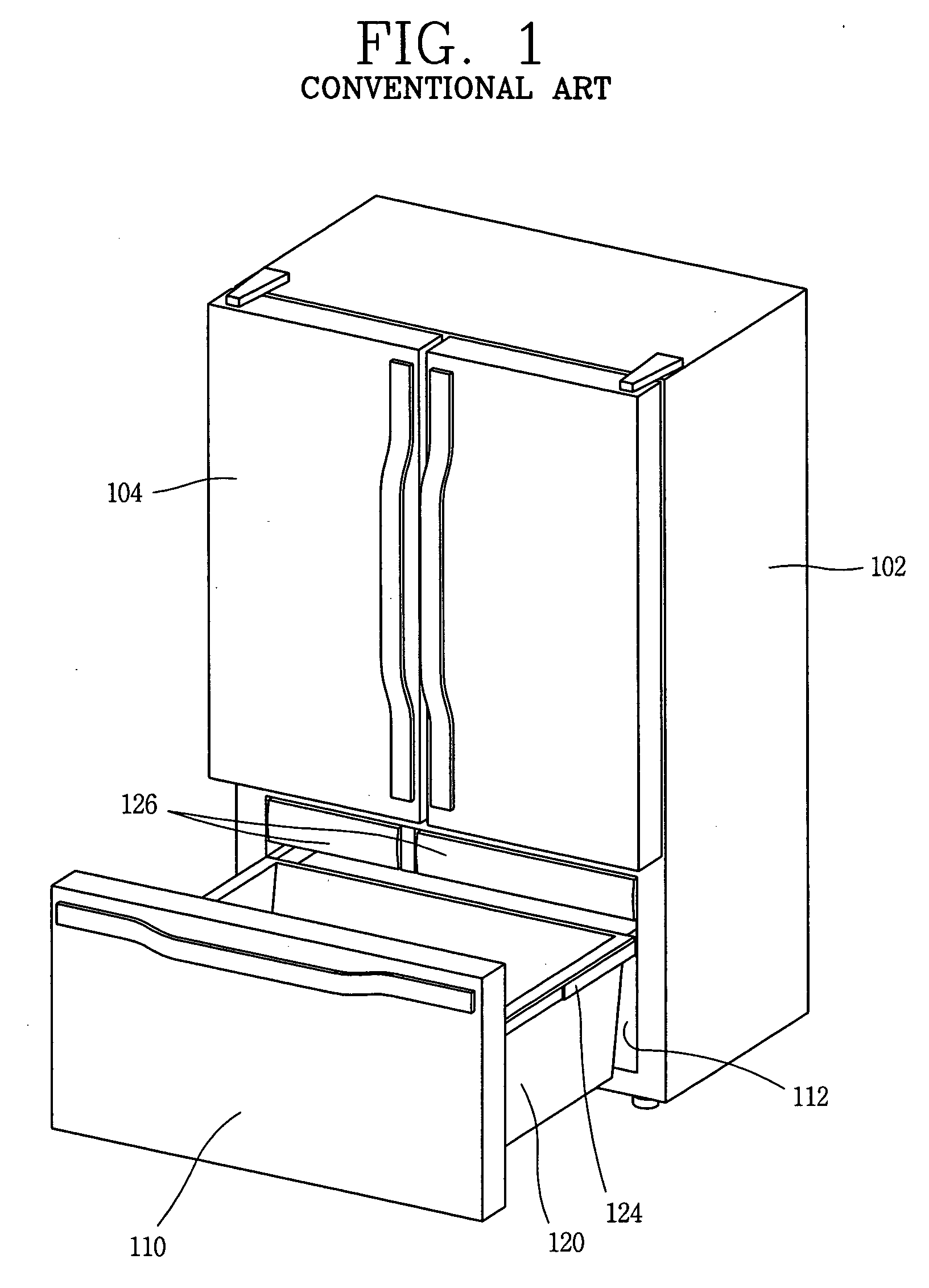
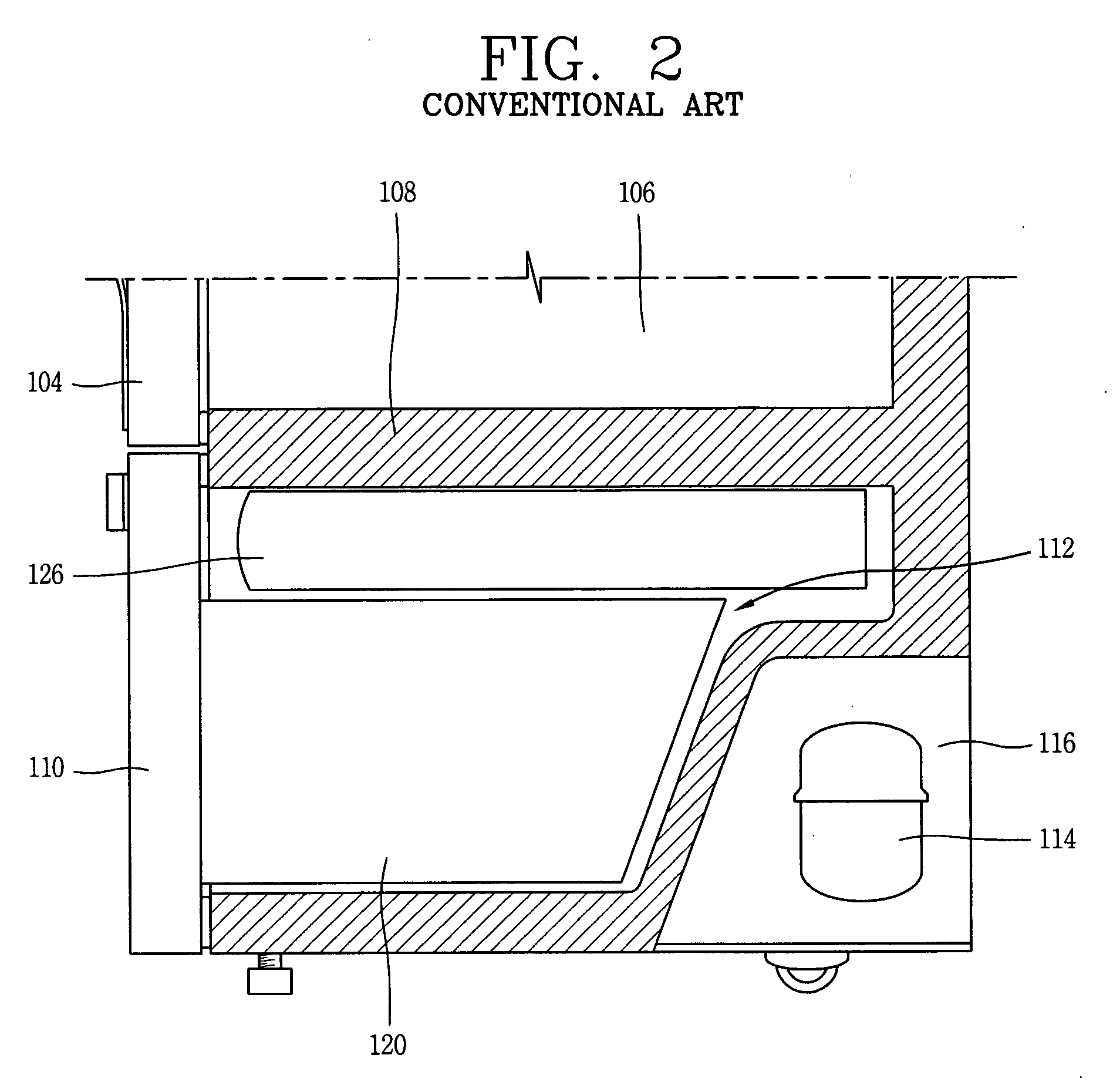
However, the conventional bottom drawer-type refrigerator has a problem in that, because the installation position of the basket is too low, a user must lower his / her posture, that is, for example, the user must bend his / her back or crouch down in order to put in or take out the food items, causing users' inconvenience.

Method used


Image

  • Bottom drawer type refrigerator having basket lift device
  • Bottom drawer type refrigerator having basket lift device
  • Bottom drawer type refrigerator having basket lift device

Examples


first embodiment

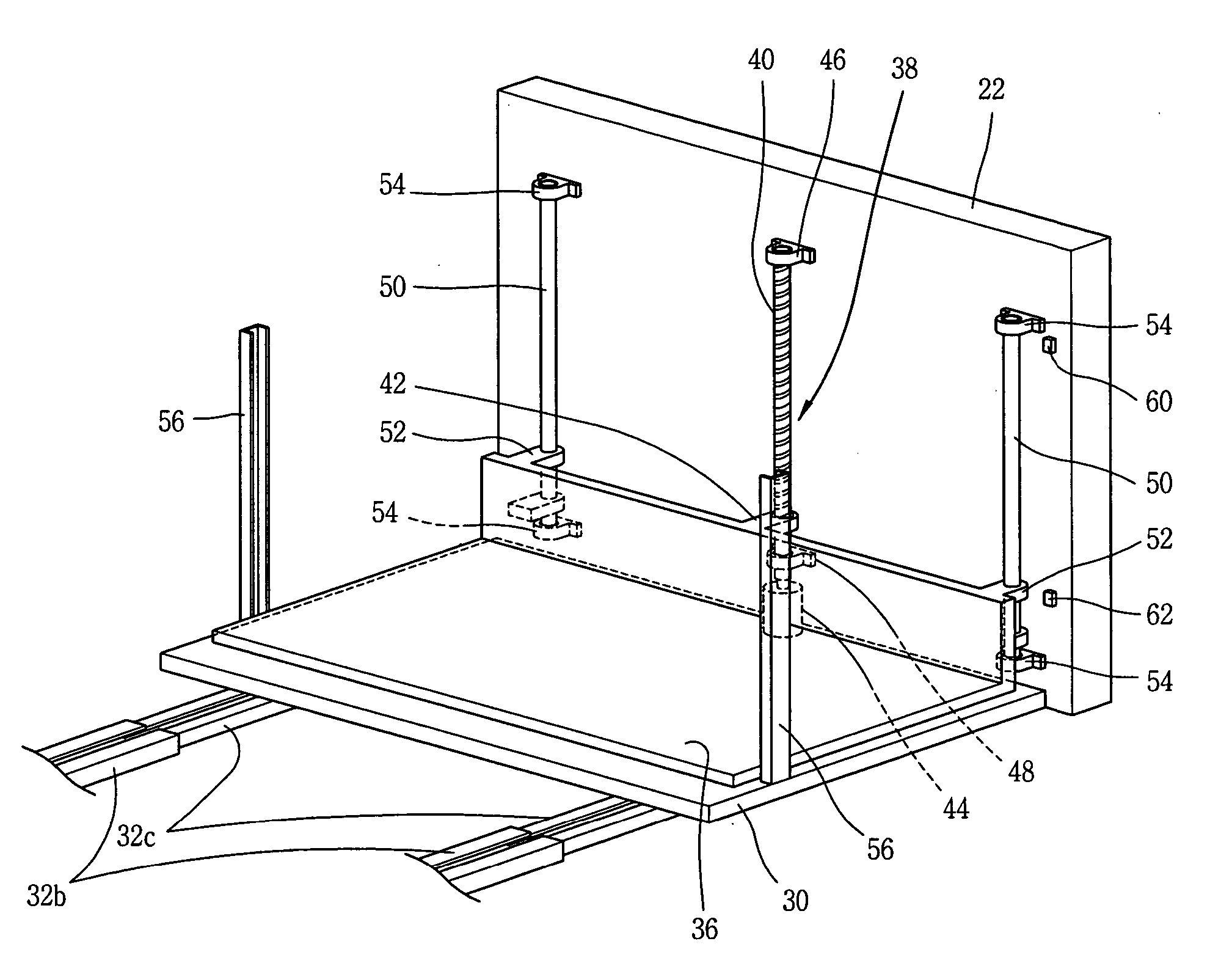
[0045]FIG. 9 shows an operation state of the basket lift device of the bottom drawer refrigerator in accordance with the present invention.

[0046] When the user wants to put or take a food item to or out of in the basket 20, the user pulls the drawer door 22 in an outward direction to draw the basket 20 out of the lower cooling chamber 28 and operates the first switch 28a mounted at the front surface of the drawer door 22. Then, a signal is applied from the first switch 28a to the controller 64 and the controller 64 applies power to the driving motor 44 to drive the driving motor 44 in a forward direction (in the direction of lifting the basket.

[0047] Then, as the lead screw 40 is rotated according to the driving of the driving motor 44, the lift arm 42 engaged with the lead screw 40 is moved up along the lead screw 40, and the lift frame 36 is thereby lifted. When the lift frame 36 reaches the highest point, the first sensor 60 senses that and applies a corresponding signal to the ...

second embodiment

[0050]FIG. 10 is a perspective view of a basket lift device of the refrigerator in accordance with the present invention.

[0051] The basket lift device in accordance with the second embodiment of the present invention has the same basic structure as the basket lift device of the first embodiment, except that the lead screw 40 is operated manually.

[0052] In detail, a square or hexagonal drive protrusion 70, onto which a tool may be inserted, is formed at an upper end of the lead screw 40. When a tool, namely, a crank handle 72, is inserted onto the drive protrusion 70 and rotated, the lead screw 40 is rotated to thereby lift up or lower down the lift frame 36.

[0053] As so far described, the refrigerator having the basket lift device has many advantages.

[0054] That is, for example, the basket lift device is provided for the basket disposed at the lower portion of the refrigerator. Thus, when the basket is drawn out, the basket can be lifted to allow the user to take a food item out ...


PUM


Abstract

In a refrigerator which includes a main body having a lower cooling chamber disposed at a lower portion of the main body, a base frame is disposed to be moved in inward / outward directions at a lower cooling chamber and has a drawer door at a front side thereof. A lift frame is disposed above the base frame, on which a basket is placed. A rotatable lead screw is vertically disposed at a rear surface of the drawer door, and a lift unit is formed at front of the lift frame for moving up and down along the lead screw. A driving unit rotates the lead screw clockwise or counterclockwise. When the basket is drawn out, the basket can be lifted to allow the user to take a food item out of the basket without bending his / her back. Thus, users' convenience can be enhanced.

Description

BACKGROUND OF THE INVENTION [0001] 1. Field of the Invention [0002] The present invention relates to a refrigerator having a basket lift device and more particularly, to a basket lift device capable of making a basket received at a lower portion of a main body lifted to enhance users' convenience. [0003] 2. Description of the Background Art [0004]FIG. 1 is a perspective view of a refrigerator and FIG. 2 is a sectional view of a lower portion of the refrigerator showing how a basket is received in a main body of the refrigerator in accordance with the conventional art. [0005] A typical bottom drawer-type refrigerator includes a main body 102 having an opened front side and a receiving space, an upper cooling chamber 106 disposed at an upper portion of the main body 102, having a pair of upper (‘French’ style side-by-side) doors 104 respectively opening swingably at both sides, for keeping food items stored therein cold, and a lower cooling chamber 112 (e.g. a freezer compartment) dis...

Claims


Application Information

Patent Timeline
IPC IPC(8): F25D17/04
CPCA47B2210/17F25D25/04F25D25/025F25D23/02F25D25/00F25D25/02
Inventor OH, SEUNG-HWANJEONG, KYUNG-HAN
Owner LG ELECTRONICS INC
Learn More