

Vessel cap and system for manufacturing the same
- Summary
- Abstract
- Description
- Claims
- Application Information
AI Technical Summary
Benefits of technology
Problems solved by technology
Method used
Image

Examples
first embodiment
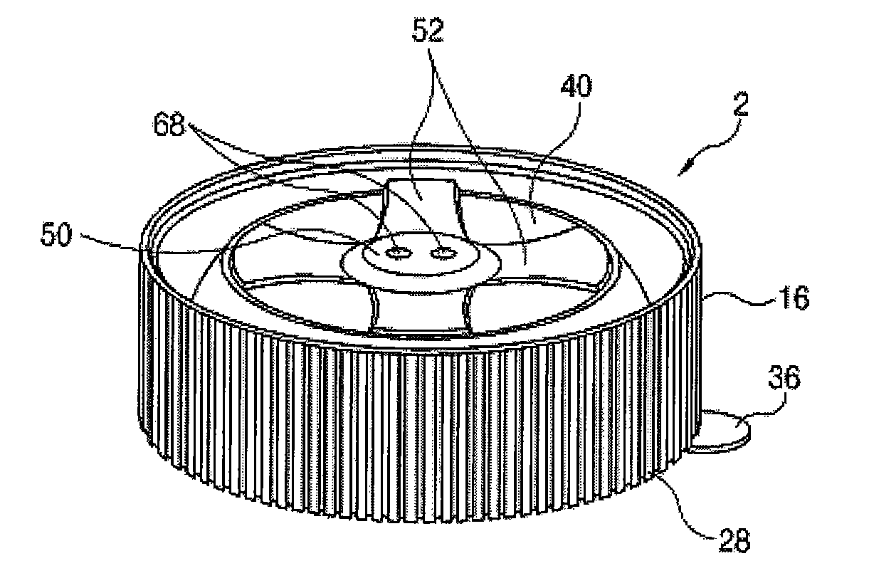
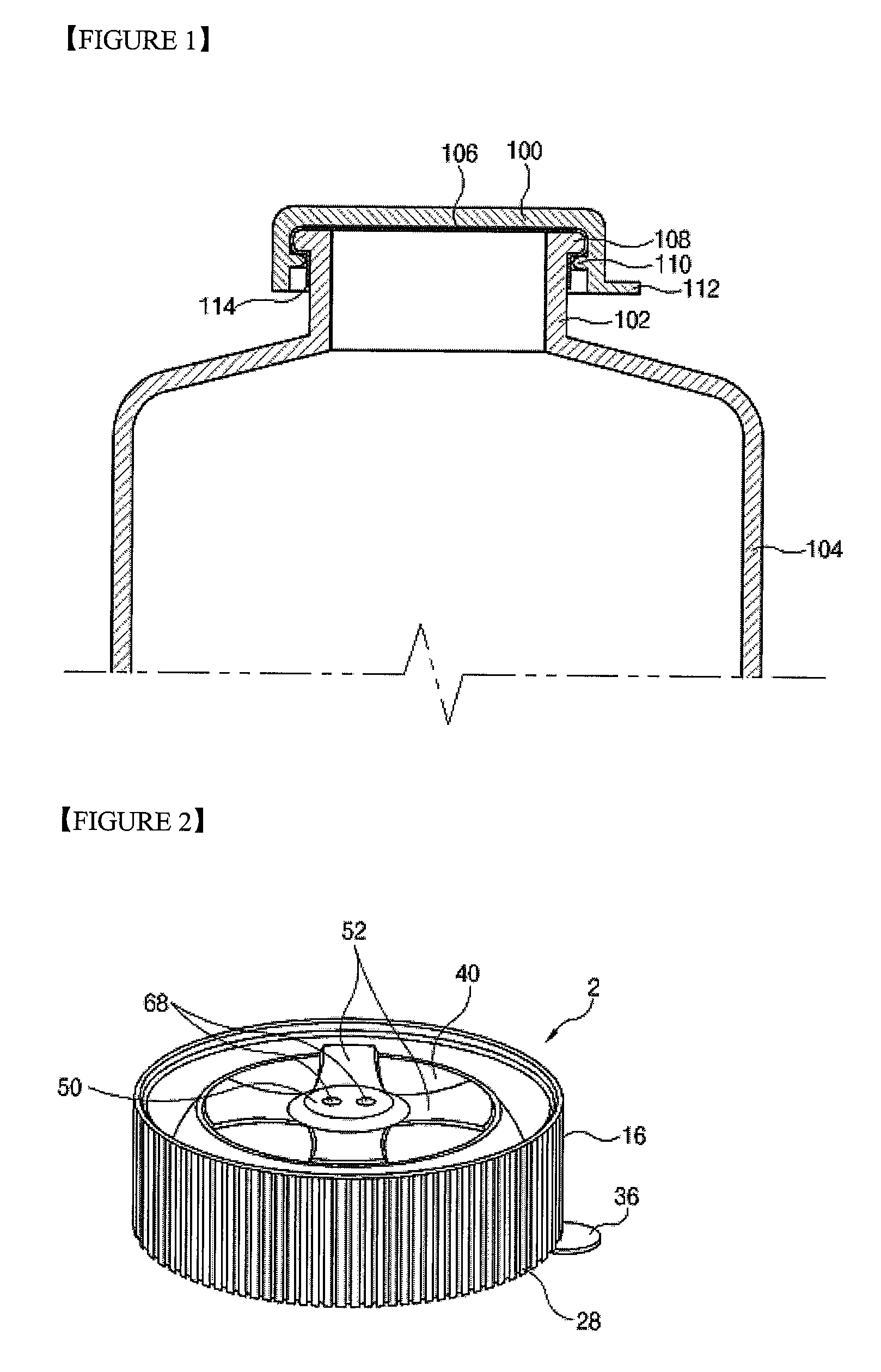
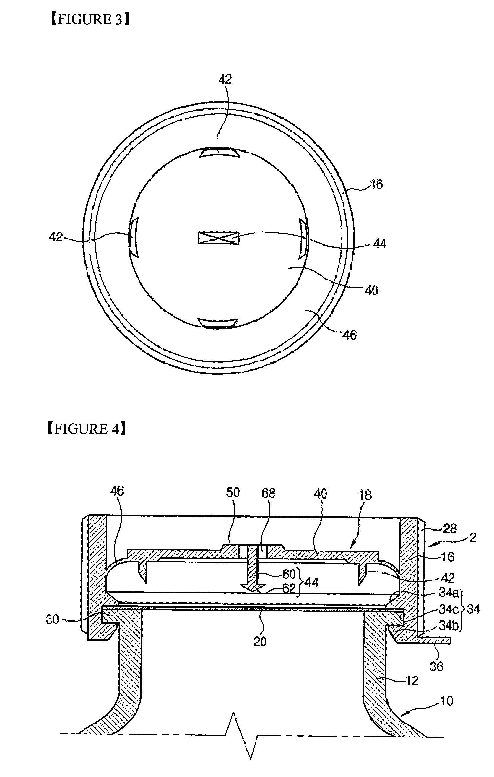
[0104]A vessel cap 2 according to the present invention comprises a body 16 mounted at a vessel inlet 12 through which a liquid material stored in a vessel 10 is discharged outwardly and having a certain space therein, and a sealing member removing unit 18 formed in the body 16 for removing a sealing member 20 attached to the vessel inlet 12 when the vessel cap 2 is detached from the vessel inlet 12 and storing the removed sealing member 20 in the vessel cap 2.
[0105]The vessel 10 stores a liquid material therein, and the sealing member 20 for sealing the vessel inlet 12 and thus protecting the liquid material is attached to the vessel inlet 12 through which the liquid material is discharged outwardly. Preferably, the sealing member 20 is formed of a material that can be easily removed by a knife, etc. such as paper, an aluminum thin plate, etc.
[0106]The body 16 has a cylindrical shape, and a plurality of concave-convex protrusions 28 for facilitating to rotate the vessel cap 2 by a ...
second embodiment
[0131]FIG. 13 is a sectional view showing a vessel cap according to the present invention.
[0132]The vessel cap according to the second embodiment is applied to a vessel having a vessel inlet 12 of a comparatively large size. A plurality of sealing member removing units 80 are disposed in the body 16 in a circumferential direction. Also, a hooking unit 84 for storing the removed sealing member in the body is installed at the center of the body 16.
[0133]That is, in the vessel cap 2 of the second embodiment, a partition plate 82 is formed at an inner circumferential surface of the body 16, and at least two mounting holes 86 are formed at the partition plate 82 in a circumferential direction. The sealing member removing unit 80 is formed at each mounting hole 86.
[0134]A mounting hole 88 is formed at a center of the partition plate 82, and the hooking unit 84 is installed at the mounting hole 88.
[0135]As shown in FIG. 14, the sealing member removing unit 80 comprises a connection portion...
third embodiment
[0147]The vessel cap according to the present invention comprises a body 150 mounted at a vessel inlet 12 through which a liquid material stored in a vessel 10 is discharged outwardly and having a certain space therein, and a sealing member removing unit 152 formed in the body 150 for removing a sealing member 20 attached to the vessel inlet 12 when the vessel cap is detached from the vessel inlet 12 and storing the removed sealing member 20 in the vessel cap.
[0148]The body 150 has a cylindrical shape, and a plurality of concave-convex protrusions 154 for facilitating to rotate the vessel cap by a user's hand are formed at an outer circumferential surface of the body 150. A mounting portion 156 detachably mounted at the vessel inlet 12 is formed at a lower portion of the body 150.
[0149]The mounting portion 156 comprises two protrusions 156a and 156b protruding from an inner circumferential surface of a lower end of the body 150 with a certain gap as a belt shape, and a hooking groov...
PUM
| Property | Measurement | Unit |
|---|---|---|
| Angle | aaaaa | aaaaa |
| Length | aaaaa | aaaaa |
| Force | aaaaa | aaaaa |
Abstract
Description
Claims
Application Information