
Vehicle bumper structure

a technology for bumpers and vehicles, applied in the direction of bumpers, vehicle components, vehicular safety arrangments, etc., can solve the problems of difficulty in sufficiently absorbing collision energy produced, and achieve the effect of preventing the occurrence of bending moments, easy and appropriately crushed, and easy and appropriately crushed

Inactive Publication Date: 2006-02-02
HONDA MOTOR CO LTD
View PDF14 Cites 16 Cited by
  • Summary
  • Abstract
  • Description
  • Claims
  • Application Information

AI Technical Summary

Benefits of technology

[0014] Also, since the hollow protrusion having the longer protruding length is provided with the slit-shaped opening, the hollow protrusion of the longer protruding length can be easily and appropriately crushed. Consequently, when a light load is applied to the hollow protrusion of the longer protruding length due to a low-speed collision, the hollow protrusion can be appropriately crushed, preventing inclination of the bumper beam. This can prevent occurrence of a bending moment on the vehicle body frame when only the hollow protrusion having the longer protruding length is crushed.
[0015] In addition, since the hollow protrusion having the longer protruding length is configured to easily appropriately crush, after it is crushed to the protruding length of the hollow protrusion having a shorter protruding length and if both the hollow protrusions are further crushed, the hollow protrusions can be crushed in a similar way. Consequently, inclination of the bumper beam is prevented also when both the hollow protrusions are crushed. This prevents occurrence of a bending moment on the vehicle body frame when both the hollow protrusions are crushed simultaneously.
[0016] Since the hollow protrusion having the longer protruding length is formed with the slit-shaped opening to be easily and appropriately crushed, when only the hollow protrusion of the longer protruding length is crushed or when both the hollow protrusions are simultaneously crushed, the crushing can be done appropriately without inclining the bumper beam 22, resulting in good absorption of collision energy.

Problems solved by technology

It is, therefore, difficult to sufficiently absorb collision energy produced in a collision by the rear bumper beam 111.

Method used


Image

  • Vehicle bumper structure
  • Vehicle bumper structure
  • Vehicle bumper structure

Examples


Embodiment Construction

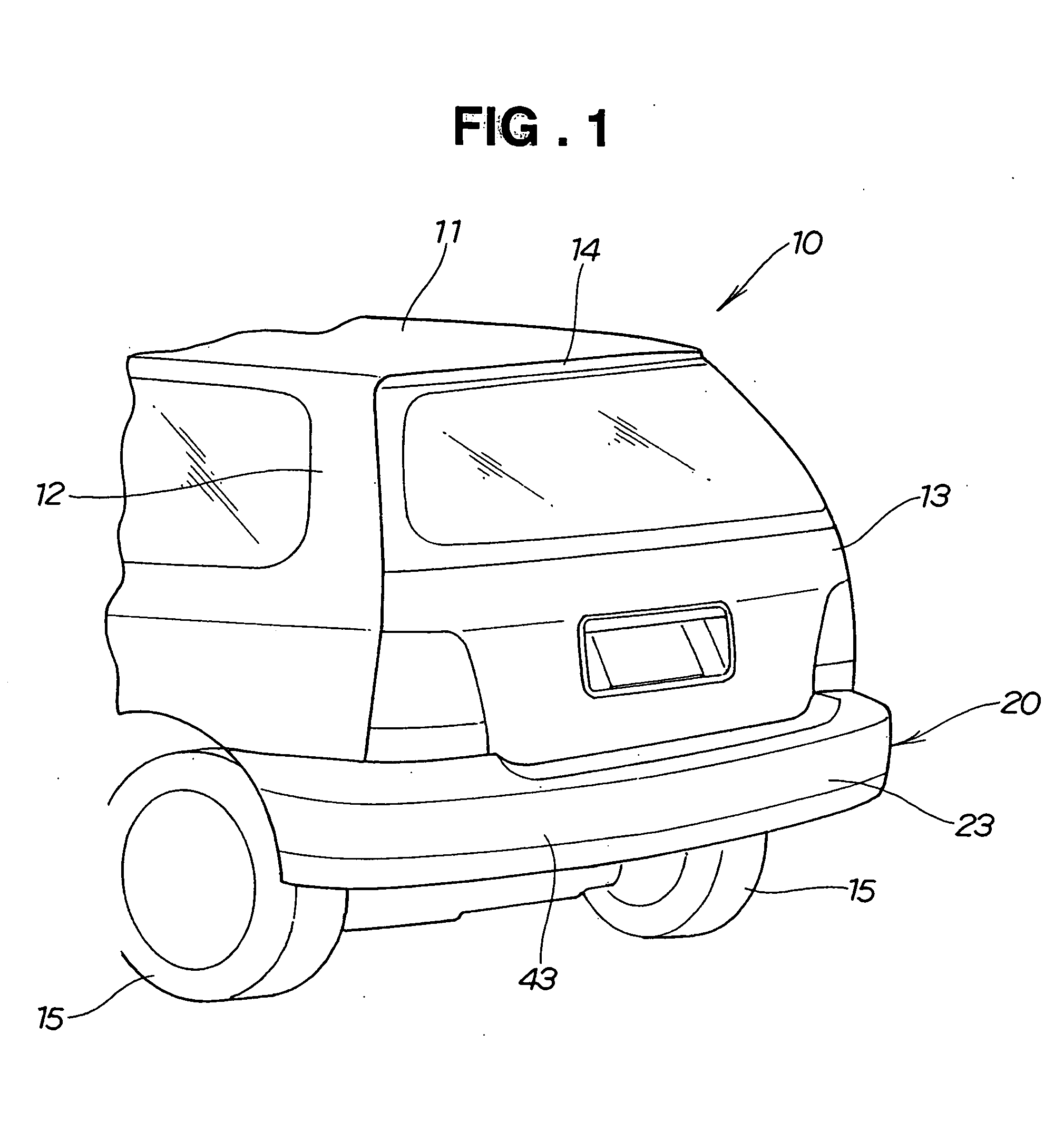
[0028] A vehicle 10 shown in FIG. 1 has a tailgate 13 provided at a rear portion 12 of a vehicle body 11, and a vehicle bumper structure 20 provided below the tailgate 13 and rearward of right and left rear wheels 15, 15.

[0029] The tailgate 13 has an upper edge portion 14 rotatably attached to the rear portion 12 of the vehicle body 11 via a hinge (not shown), thereby being supported on the hinge to be swingable to a closed position and to an open position. The closed position is a position in which the tailgate 13 closes a passenger compartment (not shown). The open position is a position in which to open the passenger compartment.

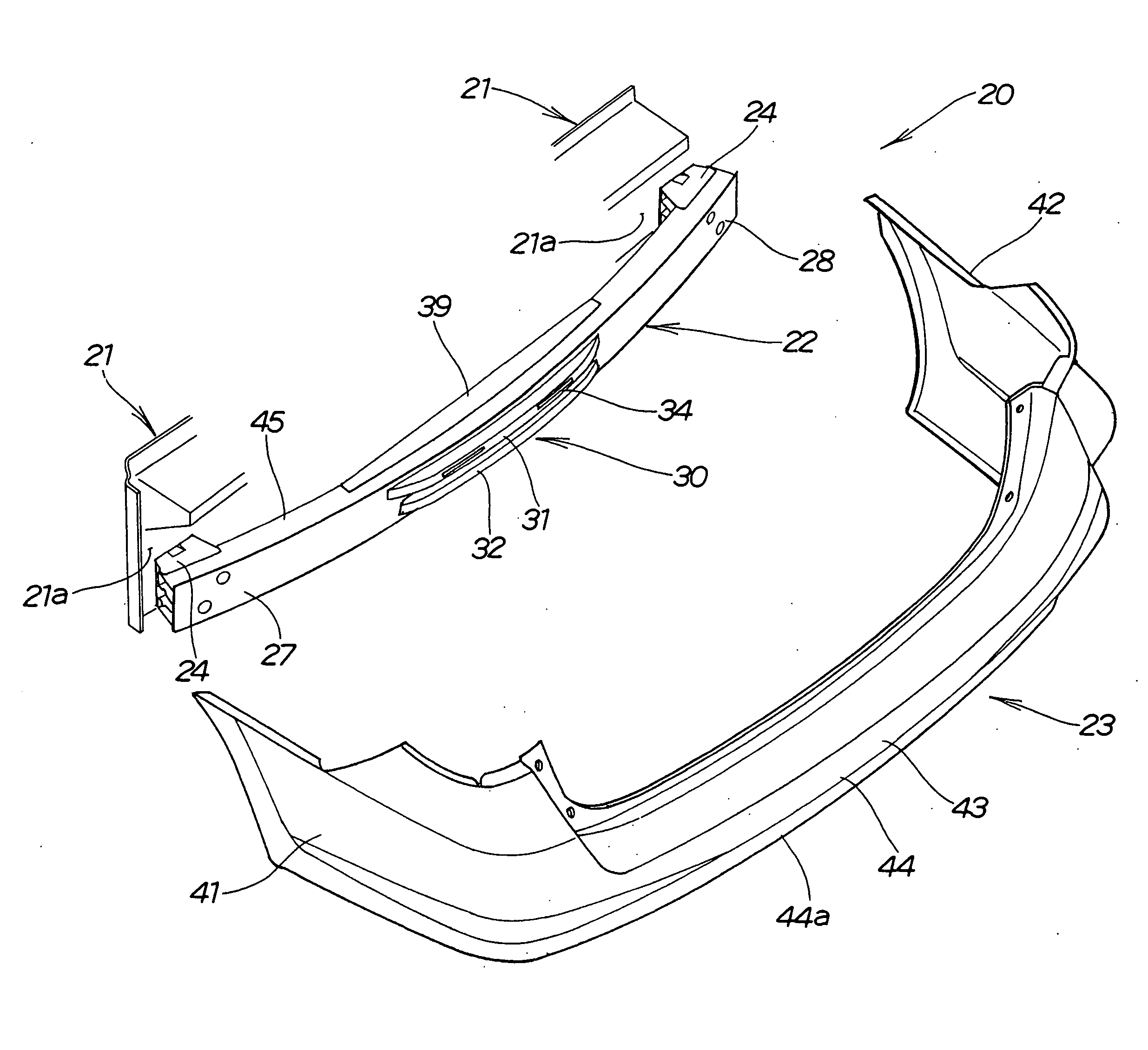
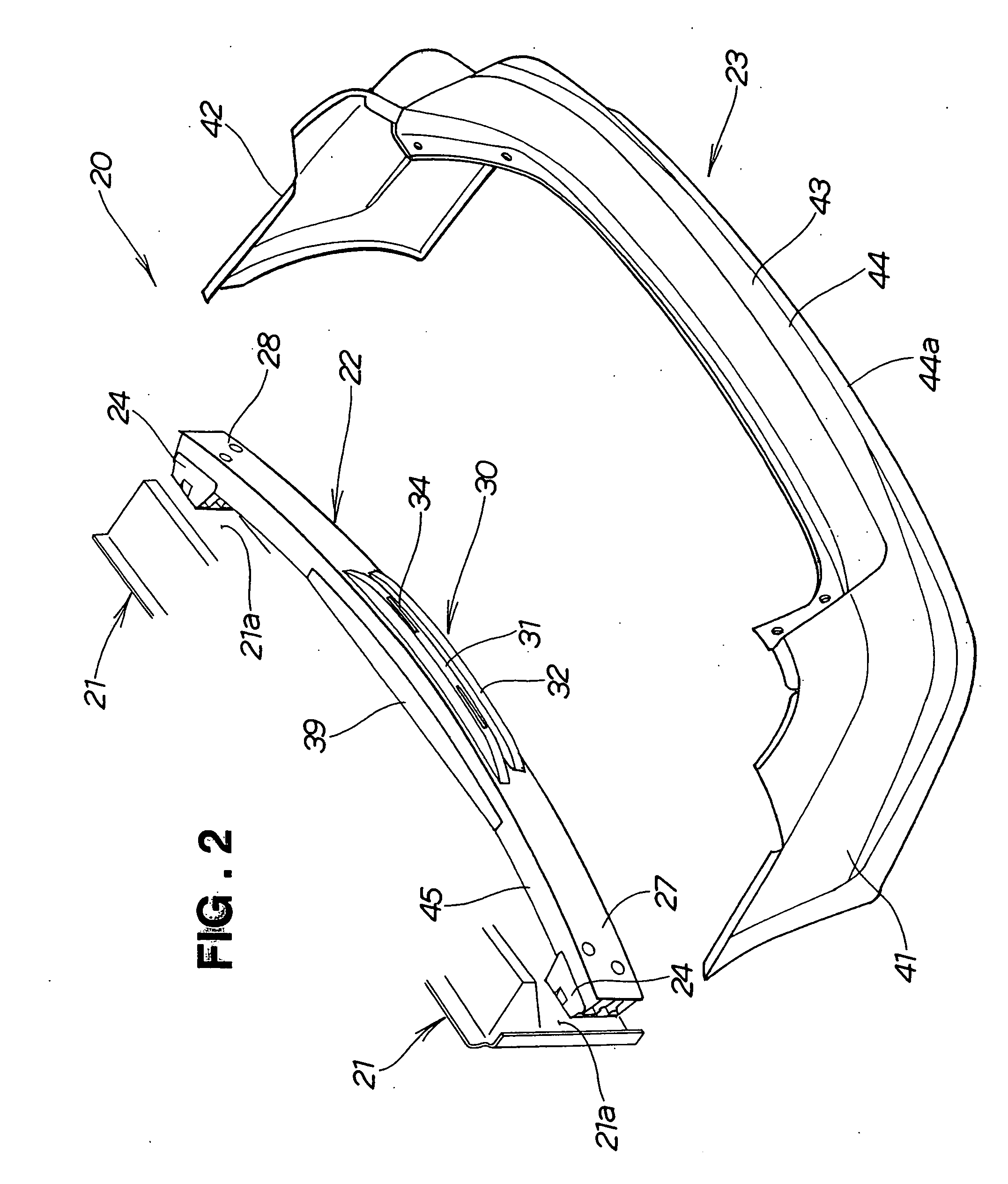
[0030] Hereinafter, the configuration of the vehicle bumper structure 20 will be described with reference to FIGS. 2 to 5.

[0031] As shown in FIG. 2, the vehicle bumper structure 20 includes a rear bumper beam (bumper beam) 22 extending transversely of the vehicle at a rear end (end) 21a of a vehicle body frame 21, and a rear bumper face (bumper face) 2...


PUM


Abstract

A vehicle bumper structure includes a cushioning member provided at a rear surface of a rear bumper beam. The cushioning member has upper and lower hollow protrusions of different protrusion lengths extending transversely of the vehicle along the rear surface of the rear bumper beam. The upper hollow protrusion, having a protruding length longer than the protruding length of the lower hollow protrusion, includes a protrusion top with a pair of light and left slit-shaped openings provided on right and left sides of a central portion for allowing easy buckling of the upper protrusion.

Description

FIELD OF THE INVENTION [0001] The present invention relates to vehicle bumper structures, and more particularly, to a vehicle bumper structure having a bumper beam extending transversely of a vehicle at an end of a vehicle body frame, and a cushioning member provided at a surface of the bumper beam. BACKGROUND OF THE INVENTION [0002] A conventional vehicle bumper structure in which, in order to absorb the impact of a vehicle collision, a cushioning member is provided at the rear of a rear bumper beam, and the rear bumper beam and the cushioning member are covered by a rear bumper cover (rear bumper face) is proposed in Japanese Patent Laid-Open Publication No. 2002-264740, for example. This bumper structure will be described with reference to FIG. 8. [0003] A vehicle bumper structure 100 shown in FIG. 8 includes a rear bumper beam 103 extending transversely of a vehicle at a rear end 102a of a side member 102 in a rear part 101 of the vehicle body, a cushioning member 104 provided a...

Claims


Application Information

Patent Timeline
Patent Type & Authority Applications(United States)
IPC IPC(8): B60R19/03
CPCB60R19/18
Inventor OMURA, KAZUOSHIGA, MASAYUKIFUKUDA, MAKOTOMIZUTANI, YOSHIMI
Owner HONDA MOTOR CO LTD
Features
  • Generate Ideas
  • Intellectual Property
  • Life Sciences
  • Materials
  • Tech Scout
  • Unparalleled Data Quality
  • Higher Quality Content
  • 60% Fewer Hallucinations
Learn More