
Arithmetic code decoding method and apparatus

Inactive Publication Date: 2006-02-02
KK TOSHIBA
View PDF5 Cites 14 Cited by
  • Summary
  • Abstract
  • Description
  • Claims
  • Application Information

AI Technical Summary

Benefits of technology

[0031] receiving and holding the generated values of the syntax el

Problems solved by technology

In addition, in order to obtain a context index required to decode an arithmetic code for a given symbol, the control must wait for completion of decoding of arithmetic codes for previous symbols, and it is difficult to increase the processing speed by pipelined parallel processes.
However, the decoding process of context-based arithmetic codes cannot be speeded up unless the operation frequency is raised.

Method used


Image

  • Arithmetic code decoding method and apparatus
  • Arithmetic code decoding method and apparatus
  • Arithmetic code decoding method and apparatus

Examples


first embodiment

(1) First Embodiment

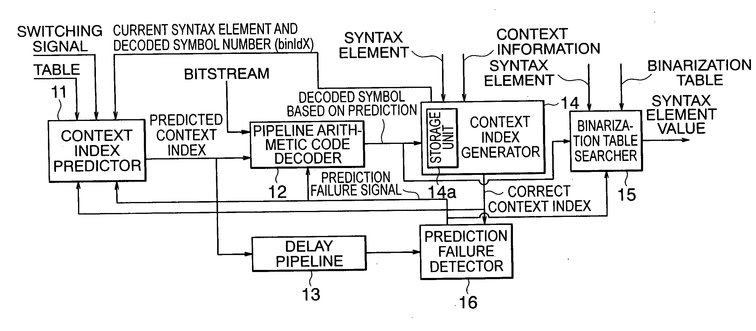
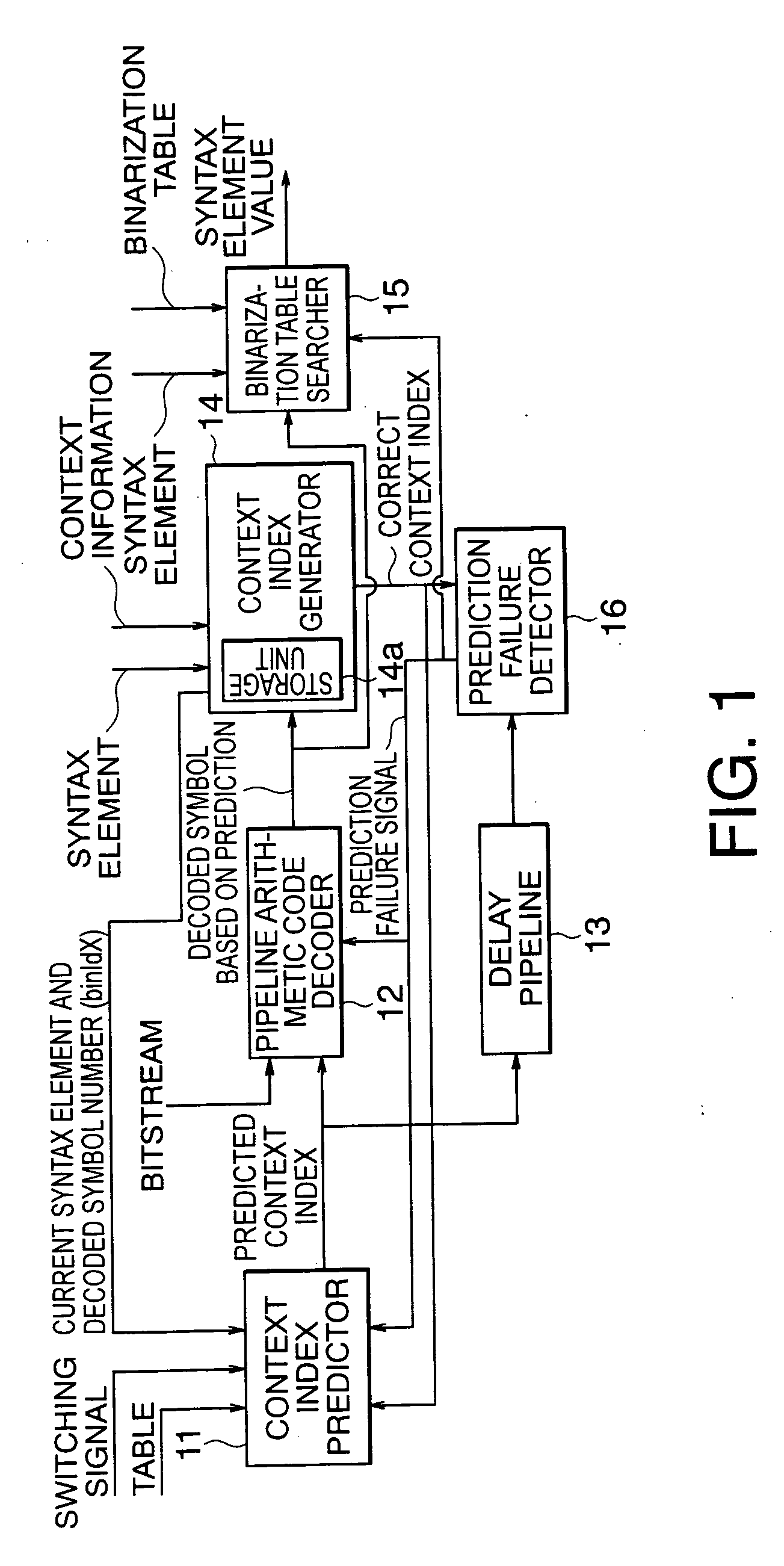
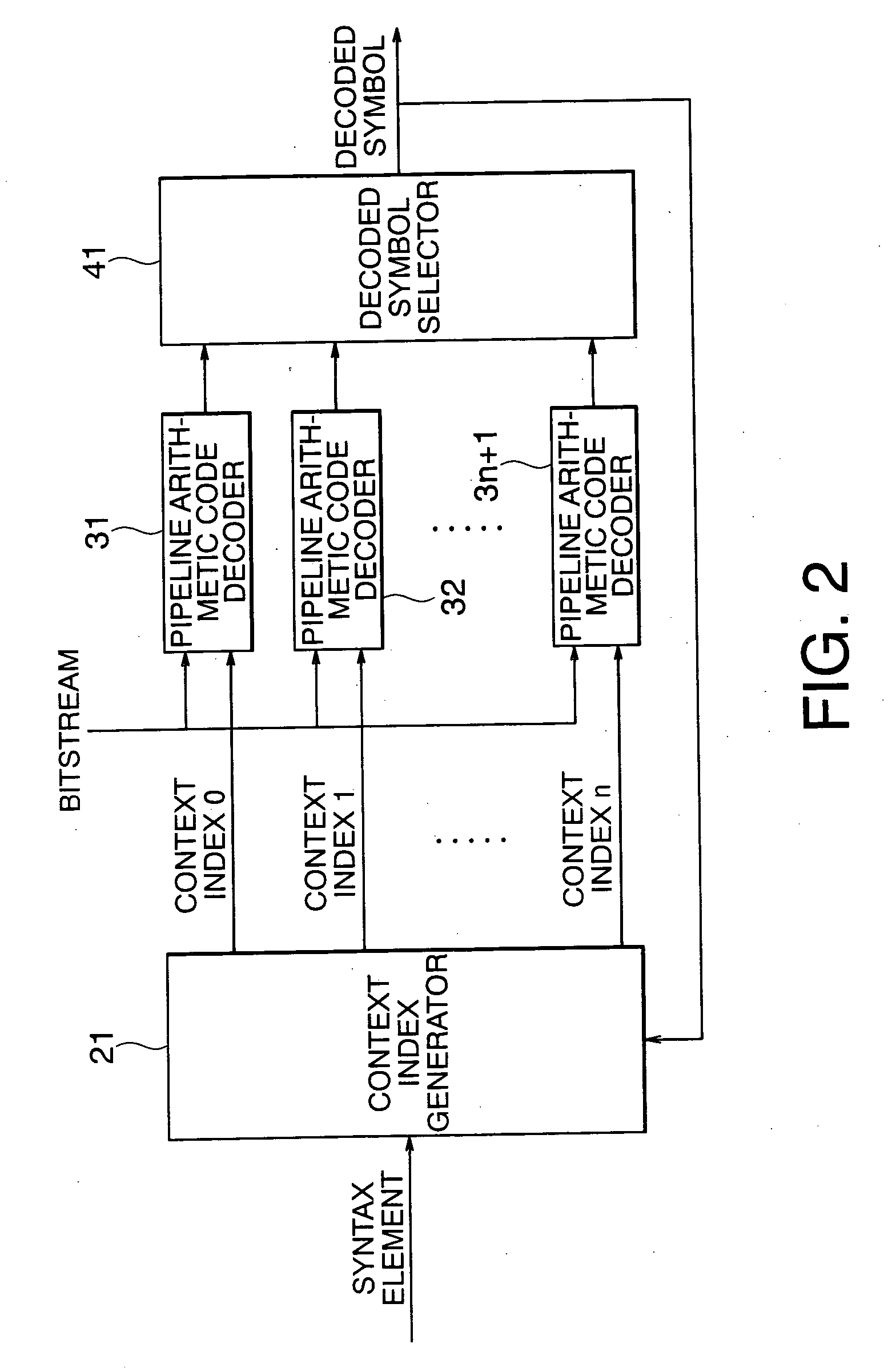
[0048]FIG. 1 shows the arrangement of an arithmetic code decoding apparatus according to the first embodiment, and FIG. 2 shows the arrangement of an arithmetic code decoding apparatus as a comparative example.

[0049] The apparatus as a comparative example comprises a context index generator 21, n (n is an integer equal to or larger than 2)+1 pipeline arithmetic code decoders 31, 32, . . . , 3n+1, and decoded symbol selector 41.

[0050] A syntax element is input to the context index generator 21. In a bitstream as encoded information, a sequence of information is specified based on syntax. The syntax element indicates the type of information allocated at a specific location. For example, when information associated with “color” is stored as the type of information at a given location on the basis of the syntax, the value of the syntax element indicates “red”, “green”, “blue”, or the like in practice.

[0051] When such syntax element is input to the context index ge...

second embodiment

(2) Second Embodiment

[0155]FIG. 12 shows the arrangement of an arithmetic code decoding apparatus according to the second embodiment of the present invention.

[0156] The arithmetic code decoding apparatus according to this embodiment comprises a context index predictor 51, pipeline arithmetic code decoder 52, delay pipeline 53, input buffer 54, context index generator 55, binarization table searcher 56, prediction failure detector 57, and output buffer 58.

[0157] As in the first embodiment, the context index predictor 51 that predicts a context index is connected before the pipeline arithmetic code decoder 52.

[0158] The context index generator 55 that generates a correct index on the basis of the history of previous decoded symbols stored in a storage unit 55a, and the binarization table searcher 56 which searches a binarization table for a syntax element value corresponding to a decoded symbol sequence are connected after the pipeline arithmetic code decoder 52.

[0159] The predict...


PUM


Abstract

According to the present invention, there is provided a arithmetic code decoding apparatus for generating a decoded symbol by decoding an input bitstream generated by encoding information, and outputting a value of a syntax element corresponding to the decoded symbol, comprising: a context index predictor which receives the syntax element indicating a type of the information included in the bitstream, predicts a context index required to decode the bitstream, and outputs the predicted context index; a pipeline arithmetic code decoder which has a plurality of stages of pipelines, receives the predicted context index and the bitstream, executes a decoding process of the bitstream using the predicted context index, and generates and outputs a decoded symbol based on prediction; a context index generator which includes a storage unit that receives and holds previous decoded symbols output before a decoded symbol at the present timing of the decoded symbols output from said pipeline arithmetic code decoder, receives the previous decoded symbols, the syntax element, and context information of the bitstream, and generates a correct context index required for decoding at the present timing; a binarization table searcher which receives the syntax element, externally acquires a predetermined binarization table corresponding to a type of the syntax element, receives the decoded symbol at the present timing output from said pipeline arithmetic code decoder, searches the binarization table using the decoded symbol for a value of the syntax element, and outputs the value of the syntax element; and a prediction failure detector which receives the correct context index output from said context index generator and the predicted context index output from said context index predictor, compares the two context indices, and outputs a prediction failure signal when the two context indices do not match, wherein when the prediction failure signal is output, said pipeline arithmetic code decoder flashes the decoding process executed using the predicted context index, re-executes a decoding process using the correct context index, and outputs a correct decoded symbol.

Description

CROSS REFERENCE TO RELATED APPLICATION [0001] This application is based upon and claims benefit of priority under 35 USC § 119 from the Japanese Patent Application No. 2004-208446, filed on Jul. 15, 2004, the entire contents of which are incorporated herein by reference. BACKGROUND OF THE INVENTION [0002] The present invention relates to an arithmetic code decoding method and apparatus. [0003] A decoding process of context-based adaptive arithmetic codes specified by the standard “H.264 Main Profile” requires considerable processing performance. [0004] To decode one symbol requires a sequence of at least four steps. In addition, in order to obtain a context index required to decode an arithmetic code for a given symbol, the control must wait for completion of decoding of arithmetic codes for previous symbols, and it is difficult to increase the processing speed by pipelined parallel processes. [0005] Other image-related processes can be speeded up by parallel processes. However, the...

Claims


Application Information

Patent Timeline
IPC IPC(8): H03M7/00
CPCH03M7/4006
Inventor NOMURA, SHUOU
Owner KK TOSHIBA
Learn More