Output performance recovering device for fuel cell and output performance recovering method for fuel cell

a technology of output performance and recovery device, which is applied in the direction of battery/fuel cell control arrangement, cell components, propulsion by batteries/cells, etc., can solve the problems of short-term degradation of performance degradation of the catalyst, and short so as to minimize the long-term degradation of the output performance of the fuel cell

Active Publication Date: 2020-03-17
TOYOTA JIDOSHA KK
View PDF15 Cites 0 Cited by
  • Summary
  • Abstract
  • Description
  • Claims
  • Application Information

AI Technical Summary

Benefits of technology

[0005]Therefore, the present disclosure provides an output performance recovering device for a fuel cell and an output performance recovering method for a fuel cell that can cope with a request for a high output for the fuel cell and that have long-term deterioration of output performance of the fuel cell minimized.
[0007]By not performing the recovery processing when it is not necessary to recover the catalyst from the short-term performance deterioration, it is possible to minimize a recovery processing frequency and to minimize long-term deterioration of output performance of the fuel cell. When it is necessary to recover the catalyst from the short-term performance deterioration and the predicted output value of the fuel cell is great, it can be predicted that a high output will be required for the fuel cell in a state in which the output performance of the fuel cell has deteriorated over a short term and thus recovery processing is performed in advance before the high output is required. Accordingly, it is possible to recover the catalyst from a state in which the output performance has deteriorated over a short term and to cope with a request for a high output to the fuel cell. When the predicted output value of the fuel cell is small, it can be predicted that a high output will not be required for the fuel cell and it is possible to cope with an output required for the fuel cell even if it is necessary to recover the catalyst from the short-term performance deterioration. In this case, by not performing the recovery processing, it is possible to minimize a recovery processing frequency and to minimize long-term deterioration of output performance of the fuel cell.
[0018]It is possible to provide an output performance recovering device for a fuel cell and an output performance recovering method for a fuel cell that can cope with a request for a high output to the fuel cell and that have long-term deterioration of output performance of the fuel cell minimized.

Problems solved by technology

In a fuel cell which is mounted as a power source for traveling in a vehicle, output performance of the fuel cell may deteriorate over a short term due to short-term deterioration in performance of a catalyst of the fuel cell.
It is also known that performance of the catalyst deteriorates over a long term by repeatedly performing such recovery processing and thus output performance of the fuel cell deteriorates over a long term (for example, see Japanese Patent Application Publication No. 2010-027297).
However, when a high output is required for the fuel cell in a state in which the output performance of the fuel cell has deteriorated over a short term as described above, there is a likelihood that the output of the fuel cell will not reach the required high output.
Accordingly, it is conceivable that the output performance is recovered from short-term deterioration by performing recovery processing to cope with a request for a high output, but when a recovery processing frequency is high as described above, there is a likelihood that the output performance of the fuel cell will deteriorate over along term.

Method used


Image

  • Output performance recovering device for fuel cell and output performance recovering method for fuel cell
  • Output performance recovering device for fuel cell and output performance recovering method for fuel cell
  • Output performance recovering device for fuel cell and output performance recovering method for fuel cell

Examples


Embodiment Construction

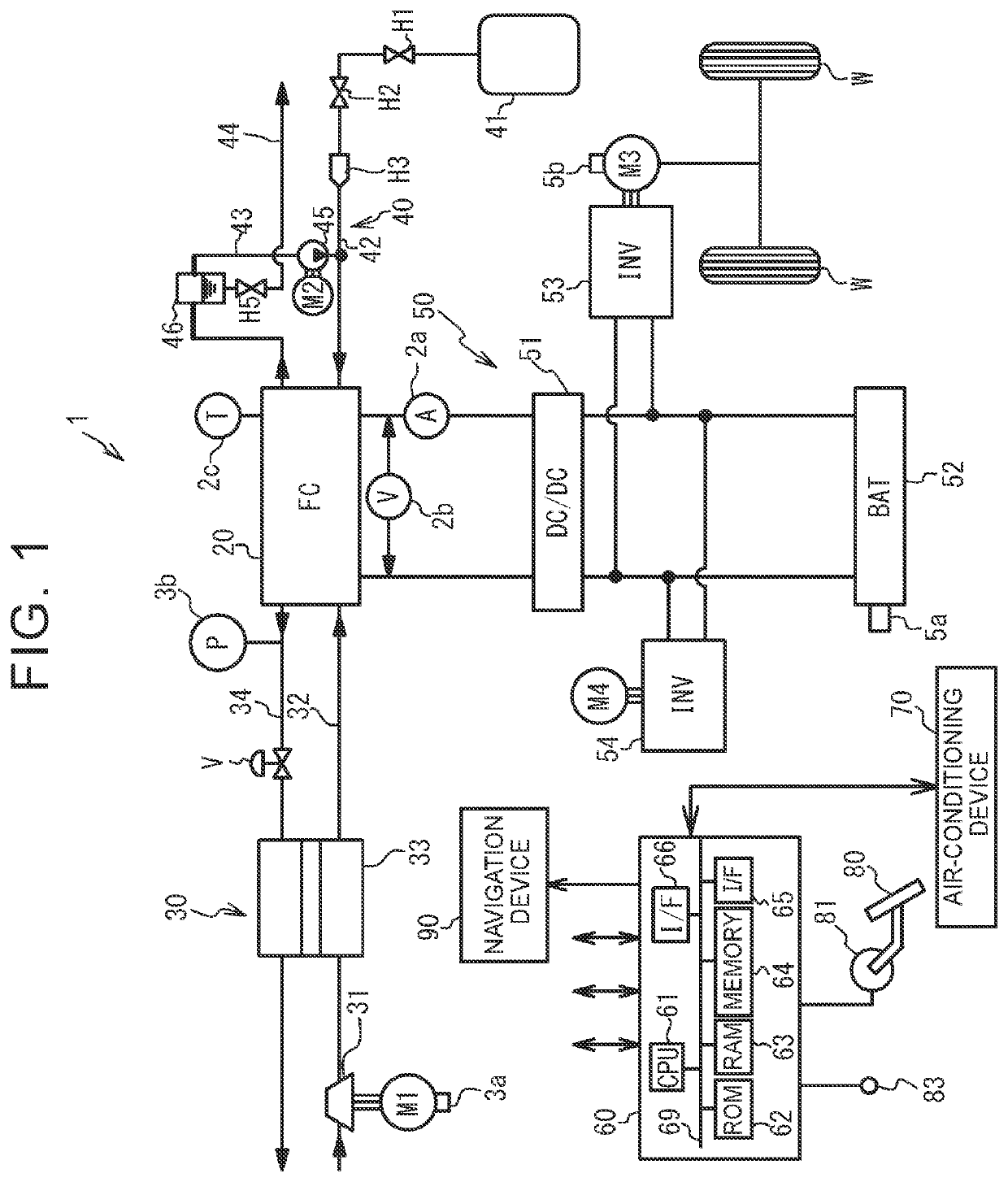
[0040]FIG. 1 is a diagram illustrating a configuration of a fuel-cell vehicle (hereinafter referred to as a vehicle). As illustrated in FIG. 1, the vehicle 1 includes an oxidant gas piping system 30, a fuel gas piping system 40, a power system 50, and a control device 60. The fuel cell 20 is supplied with oxidant gas and fuel gas and generates power. The oxidant gas piping system 30 supplies air containing oxygen as the oxidant gas to the fuel cell 20. The fuel gas piping system 40 supplies hydrogen gas as fuel gas to the fuel cell 20. The power system 50 charges and discharges a system with power. The control device 60 comprehensively controls the vehicle 1 as a whole. The fuel cell 20 is of a solid polymer electrolyte type and has a stacked structure in which a plurality of cells are stacked. A current sensor 2a and a voltage sensor 2b that detect an output current and an output voltage and a temperature sensor 2c that detects a temperature of the fuel cell 20 are attached to the ...


PUM

PropertyMeasurementUnit
temperatureaaaaaaaaaa
current densityaaaaaaaaaa
temperatureaaaaaaaaaa

Abstract

An output performance recovering device for a fuel cell includes: a diagnosis unit configured to determine whether it is necessary to recover a catalyst of a fuel cell mounted as a power source for traveling in a vehicle from short-term performance deterioration; a recovery unit configured to control a voltage of the fuel cell and to perform recovery processing for recovering the catalyst from the short-term performance deterioration; a calculation unit configured to calculate a parameter correlated with a predicted output value of the fuel cell which has been predicted to be output on a scheduled traveling route of the vehicle based on a gradient of the scheduled traveling route of the vehicle and a predicted vehicle speed of the vehicle on the scheduled traveling route; and a determination unit configured to determine whether the parameter indicates the predicted output value is greater than a first threshold value.

Description

INCORPORATION BY REFERENCE[0001]The disclosure of Japanese Patent Application No. 2016-196715 filed on Oct. 4, 2016 including the specification, drawings and abstract is incorporated herein by reference in its entirety.BACKGROUND1. Technical Field[0002]The disclosure relates to an output performance recovering device for a fuel cell and an output performance recovering method for a fuel cell.2. Description of Related Art[0003]In a fuel cell which is mounted as a power source for traveling in a vehicle, output performance of the fuel cell may deteriorate over a short term due to short-term deterioration in performance of a catalyst of the fuel cell. In this case, a process for recovering performance of the catalyst from the short-term performance deterioration by controlling an output voltage of the fuel cell is known. It is also known that performance of the catalyst deteriorates over a long term by repeatedly performing such recovery processing and thus output performance of the fu...

Claims


Application Information

Patent Timeline
Patent Type & Authority Patents(United States)
IPC IPC(8): H01M8/10H01M8/04828H01M4/92H01M16/00B60L58/33B60L58/40B60L50/72B60L50/51H01M8/04537B60L1/00B60L7/14
CPCH01M8/0494H01M16/006B60L7/14B60L58/40B60L50/72H01M8/04559H01M4/92B60L1/003B60L50/51B60L58/33H01M8/10H01M2250/20Y02T90/34Y02E60/10Y02E60/50Y02T10/70Y02T90/40
Inventor MATSUSUE, MASAAKIARAKI, YASUSHIITO, MASAYUKI
Owner TOYOTA JIDOSHA KK
Why Eureka
Try Eureka