
Recessed sealed lighting fixture

a technology for sealing lighting fixtures and recessed lights, which is applied in the direction of lighting and heating apparatus, lighting support devices, light source combinations, etc. it can solve the problems of less attractive light fixtures, less suitable for medical facilities, and abrasion of unsealed light fixtures, so as to facilitate easy cleaning of diffusers and reduce dust and bacteria. , the effect of reducing the collection

Inactive Publication Date: 2006-02-02
FOCAL POINT
View PDF28 Cites 74 Cited by
  • Summary
  • Abstract
  • Description
  • Claims
  • Application Information

AI Technical Summary

Benefits of technology

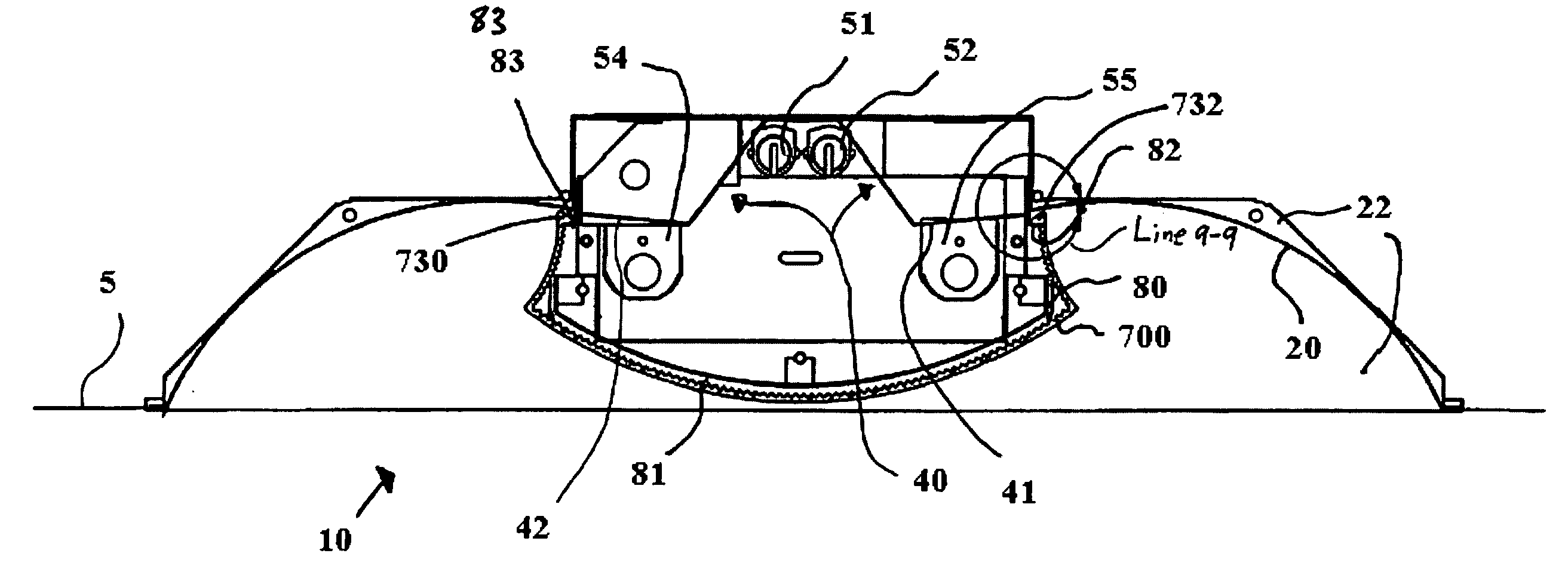
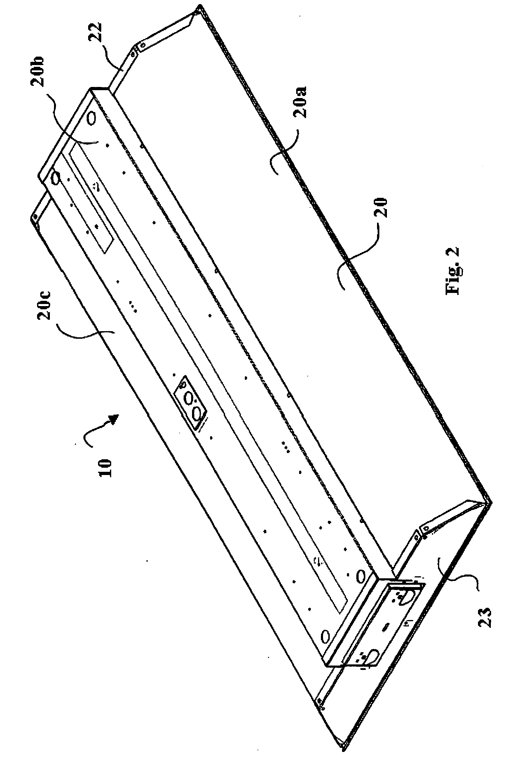
[0010] In an embodiment of the present invention, a light fixture is provided that has a concave-shaped structural reflector that also acts as the fixture enclosure. Two end caps are welded to the structural reflector so that the combination of the end caps and the structural reflector forms a rectangular like opening. Inside the opening a reflector is positioned longitudinally along the center of the rectangular opening. The reflector has a first optics area and a second optics area and a third optics area. Two high output linear light sources are mounted adjacent the first optics area. A first lower output linear light source is mounted adjacent the second optics area and a second lower output linear light source is mounted adjacent the third optics area. A curved diffuser is sealably mounted to the structural reflector so as to substantially seal the interior portion of the light fixture from dust accumulation. Preferably the curved diffuser has a smooth exterior surface so as to minimize dust and bacteria collection on the exterior surface and to facilitate easy cleaning of the diffuser.

Problems solved by technology

Such sealed light fixtures are typically used in heavy commercial or industrial settings where the environment can be abusive to unsealed light fixtures because of moisture, dust and the like.
While functional, these light fixtures suffer from being relatively less attractive.
While the various light fixtures described above are effective in their respective environments, they are less suitable for use in a medical facility.

Method used


Image

  • Recessed sealed lighting fixture
  • Recessed sealed lighting fixture
  • Recessed sealed lighting fixture

Examples


Embodiment Construction

[0027] Light fixtures for use in medical facilities have requirements somewhat different than the requirements of a typical office. The requirements are even more unique when the light fixture is installed directly above the patient in a hospital room. In such a circumstance it is desirable that the light fixture provide an attractive appearance but be easy to clean so as to avoid or at least minimize the accumulation of dust and germs. In addition, it is desirable to have a light fixture that has at least two modes of operation, an ambient mode and an examination mode.

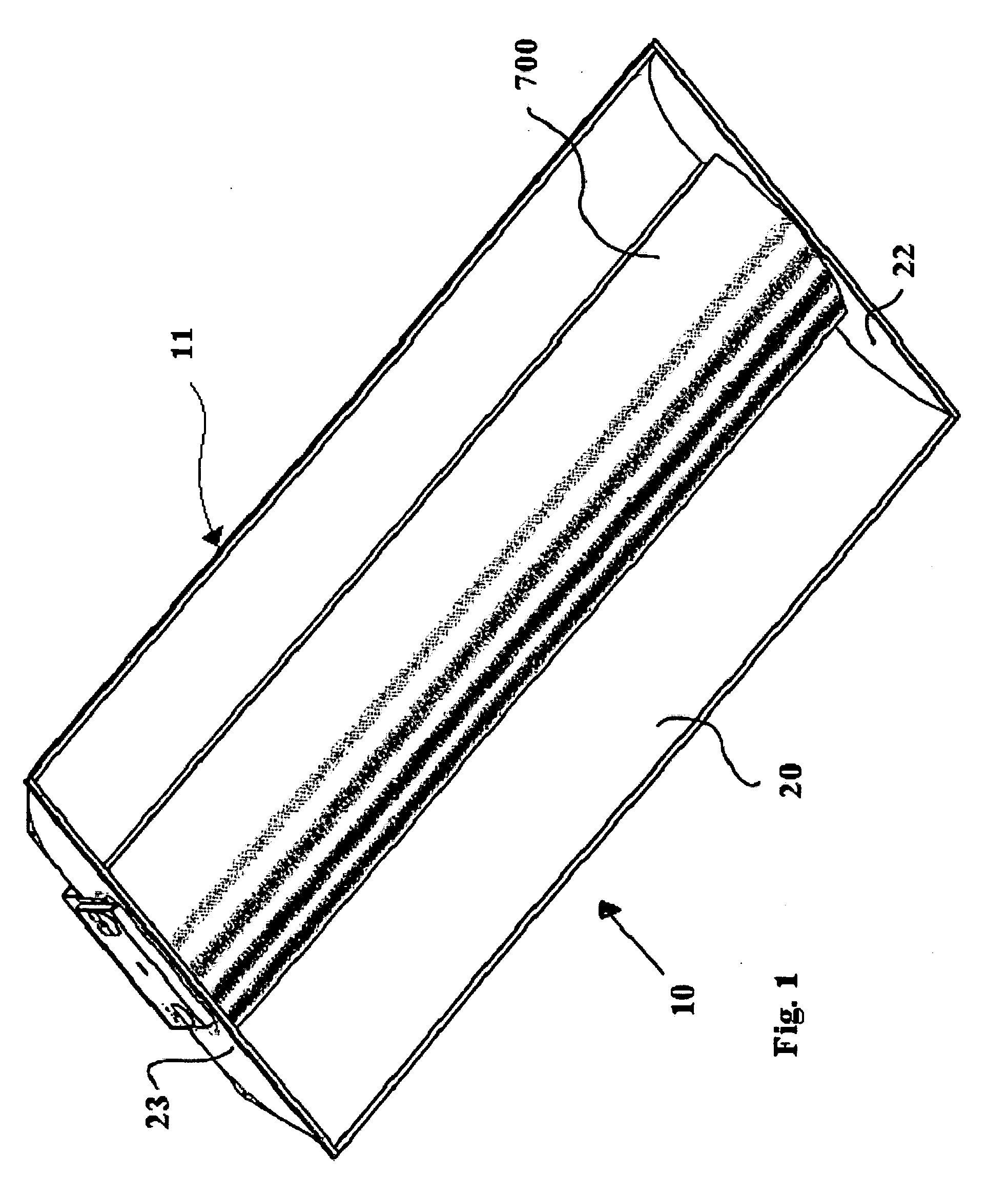
[0028]FIG. 1 is an illustration of an exemplary embodiment of a sealed light fixture 10. As depicted, the light fixture 10 comprises a structural reflector 20, an end cap 22, an end cap 23 and a diffuser 700. A light fixture housing 11 includes the structural reflector 20, the end cap 22 and the end cap 23. The preferred construction, as described below, provides an aesthetically pleasing light fixture that is capabl...


PUM

PropertyMeasurementUnit
Lengthaaaaaaaaaa
Poweraaaaaaaaaa
Areaaaaaaaaaaa

Abstract

In an embodiment, a recessed light fixture includes a structural reflector and two end caps that form a light fixture housing. A first, second and third optics areas are provided. At least one first light source type is mounted near the first optics area. A second light source type is mounted near the second optics area and the second light source type is mounted near the third optics areas, the second light source type having a light output level substantially lower than the light output level of the first light source type. A diffuser is configured to sealably mount to the light fixture housing so as to substantially seal an interior portion of the light fixture. In operation, the light fixture can be switch between an ambient mode and an examination mode while providing a cost effective and attractive design.

Description

BACKGROUND OF THE INVENTION [0001] The application claims priority to U.S. Provisional Application No. 60 / 592,509 filed Jul. 29, 2004, which is incorporated in its entirety herein. [0002] 1. Field of the Invention [0003] The present invention relates to recessed light fixtures, more specifically to recessed light fixtures for use in medical facilities. [0004] 2. Description of Related Art [0005] Recessed light fixtures are known, and are typically used when it is desirable to minimize the projection of the light fixture below the ceiling surface. Recessed light fixtures, as opposed to light fixtures that substantially extend below the ceiling surface, tend to be more aesthetically appealing and provide a cleaner look when installed. Thus, recessed light fixtures tend to be used in commercial settings such as offices and the like. [0006] Some recessed light fixtures use a curved reflective surface mounted in a rectangular shaped housing. The light source or sources is / are mounted ins...

Claims


Application Information

Patent Timeline
IPC IPC(8): F21V5/00
CPCF21S8/02F21V3/04F21V5/02F21V15/015Y10T29/49826F21V17/164F21W2131/20F21Y2103/00F21Y2113/00F21V17/14
Inventor CHUNG, CASEYCODY, JILLSTOLTE, BRANDONPENA, MARCELINOTHORNTON, MICHAEL
Owner FOCAL POINT
Learn More