Bearing support for motors

Inactive Publication Date: 2006-02-09
BLACK & DECKER INC
View PDF5 Cites 36 Cited by
  • Summary
  • Abstract
  • Description
  • Claims
  • Application Information

AI Technical Summary

Benefits of technology

[0006] Accordingly, the present invention is directed to a motor mount

Problems solved by technology

Assembly of the various motor components may require significant labor/expense to assemble.
Manufacturing a motor in this fashion may be time consuming as personnel are required to manipulate the components to ensure proper alignment.
This may increase labor and the overall time required to assemble the motor.
Furthermore, current motors may require a significant number of electrical terminals (connections) t

Method used


Image

  • Bearing support for motors
  • Bearing support for motors
  • Bearing support for motors

Examples


Example

[0017] Reference will now be made in detail to the presently preferred embodiments of the invention, examples of which are illustrated in the accompanying drawings. It is to be appreciated that generally corresponding structures are provided with corresponding reference numbers.

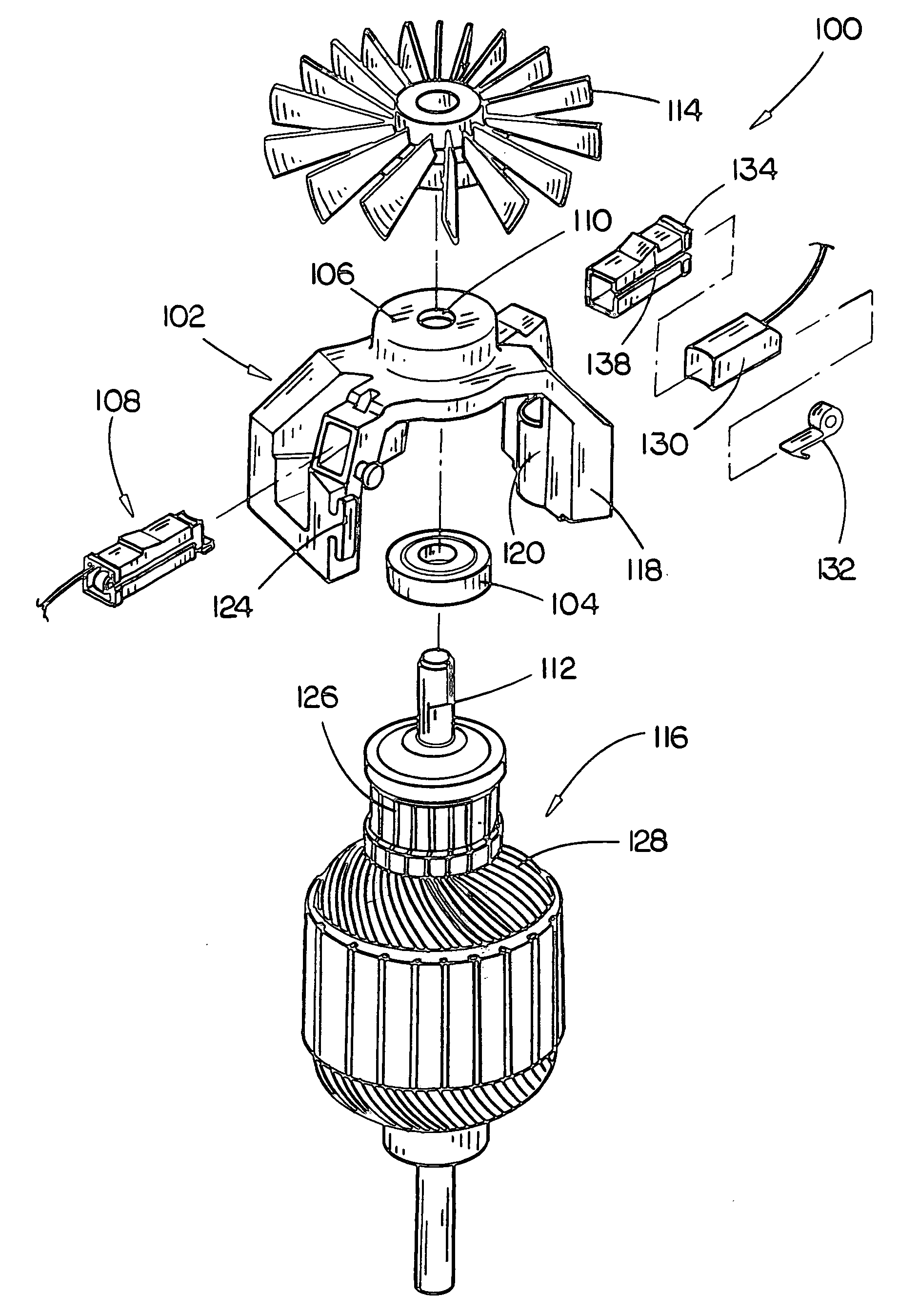
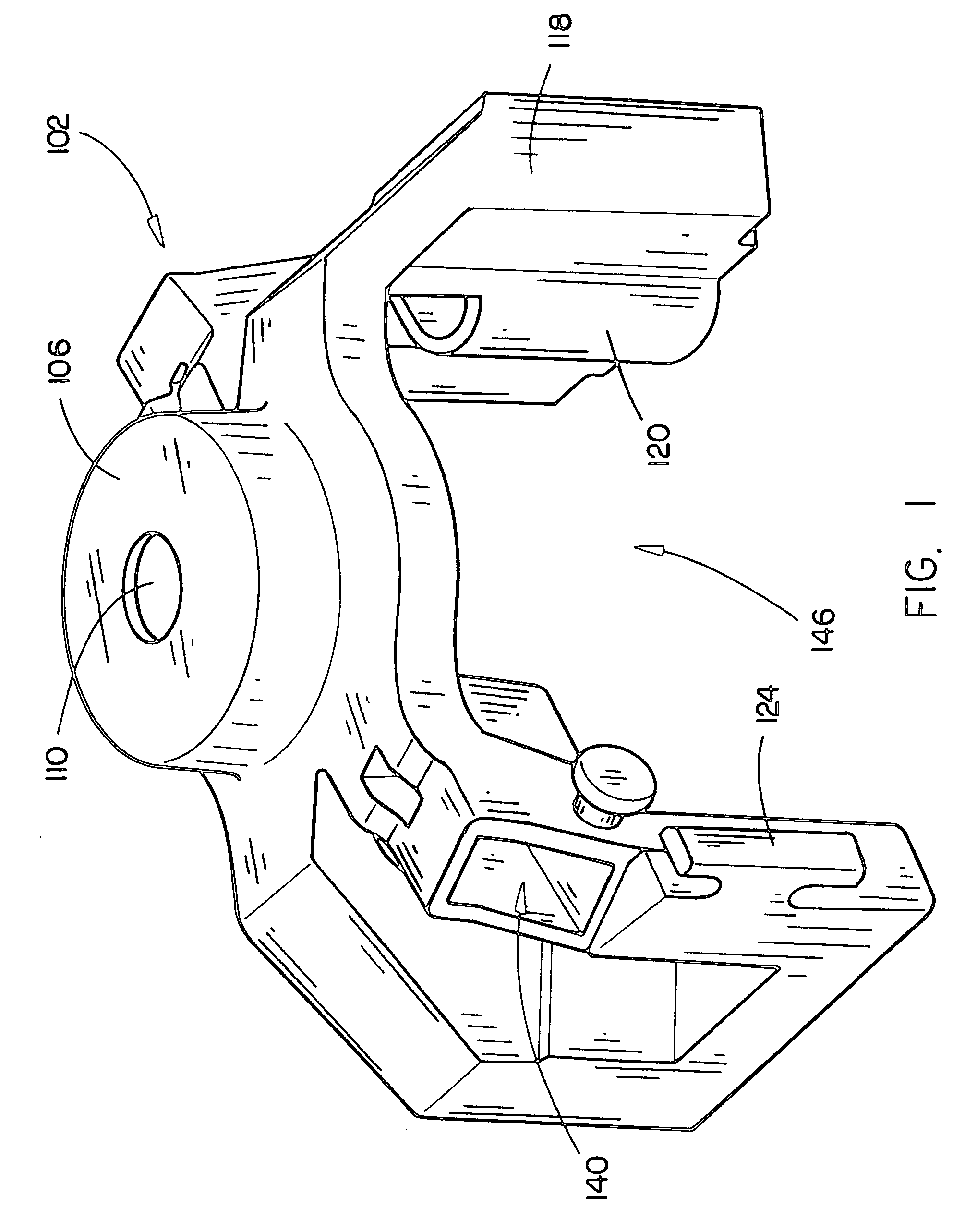
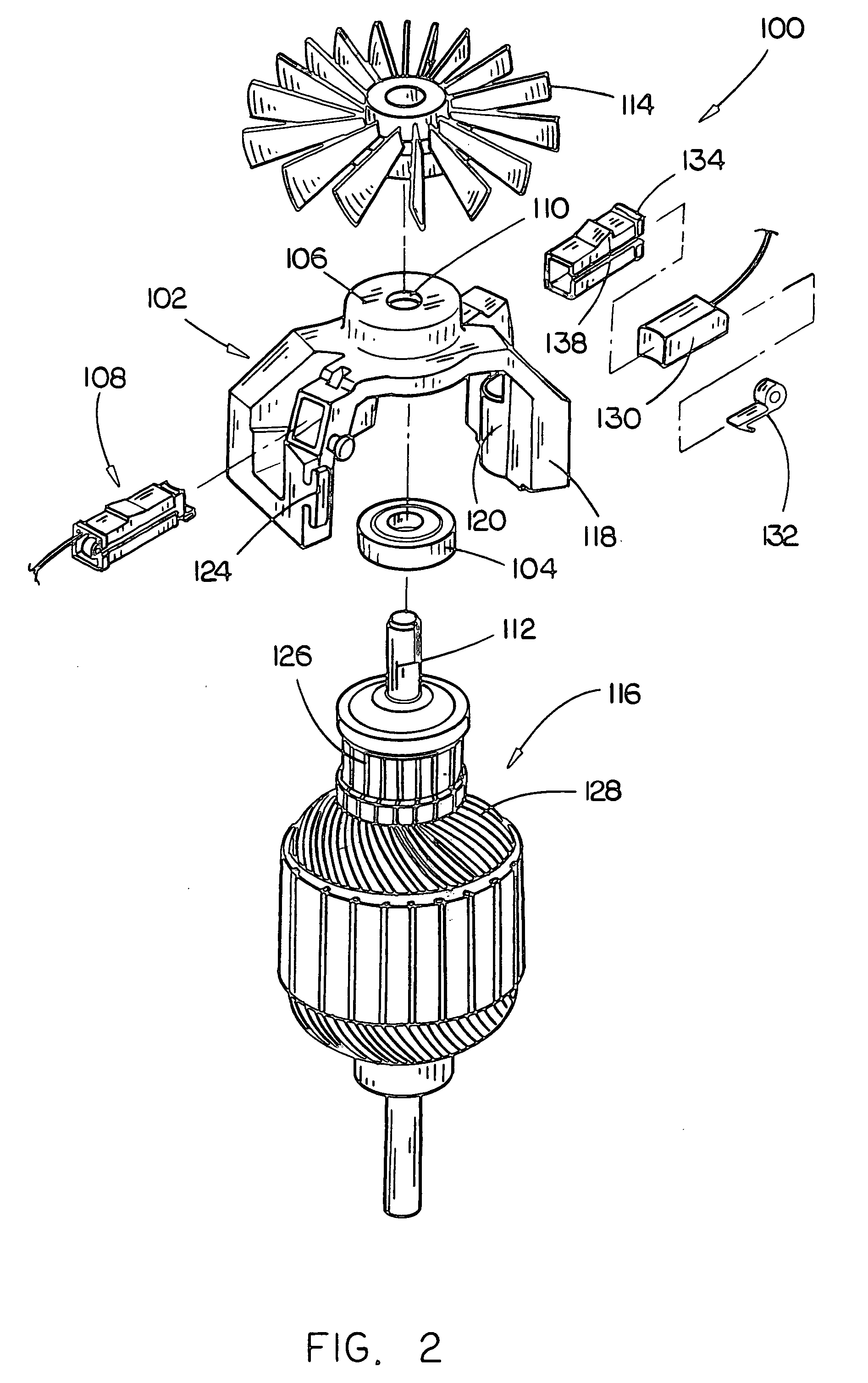
[0018] Referring to FIGS. 1 through 4, in the present embodiment of the invention, a motor mounting 102, included in an electrical motor 100, is discussed. An electrical motor 100 of the present invention may implement the mounting 102 for aiding in efficient assembly and repair. Further, a motor 100 in accordance with an aspect of the invention may permit the inclusion of a brush assembly 108 or a preassembled brush subassembly which may aid in efficient final assembly of the motor 100. Moreover, a motor 100 in accordance with the present invention may minimize the number of terminals required for coupling the stator or field wire to the brush assembly.

[0019] In the present embodiment, the mounting 102 is ...


PUM


Abstract

A motor mounting and a motor configured for simplified assembly. The motor mounting is configured for including a bearing, the bearing for receiving a rotor shaft therein. The motor mounting is configured to accept a brush assembly received from an exterior surface. The brush assembly and motor mounting may be constructed to permit coupling in a tool-less manner. The brush assembly and mounting may be secured by a friction fit engagement.

Description

CROSS REFERENCE [0001] The present application claims priority under 35 U.S.C. §119(e) to U.S. Provisional Patent Application Ser. No. 60 / 599,405, entitled: Bearing Support for Motors, filed on Aug. 6, 2004, which is hereby incorporated by reference in its entirety.FIELD OF THE INVENTION [0002] The present invention generally relates to the field of motors and more particularly to a bearing mounting having an integrated brush holding capability and direct support for a stator, or field magnet, wire for universal motors. BACKGROUND OF THE INVENTION [0003] Motors and in particular, universal motors proliferate everyday life in modern societies. Universal motors are particularly effective for utilization in devices in which size and weight are of concern. Power tools such as portable compressors, hand power tools (e.g., drills, circular saws, and the like), and the like typically implement universal motors. Due to the extensive use of motors in everyday situations, the efficient manufa...

Claims


Application Information

Patent Timeline
IPC IPC(8): H01R39/38
CPCH01R39/385H02K5/1732H02K5/148H01R39/415
Inventor MCFARLAND, DALTON E.THURMOND, BOBBY O. JR.VERNAGLIA, STEPHEN F.ROGERS, STEPHEN D.WOOD, MARK W.BREEDEN, JAMES T.
Owner BLACK & DECKER INC
Why Eureka
Try Eureka