Drift compensation in a flash memory

a flash memory and drift compensation technology, applied in the field of nonvolatile memory management, can solve the problems of inability to guarantee the reliability of error correction procedures, limited block size of flash cells,

Active Publication Date: 2006-02-09
WESTERN DIGITAL ISRAEL LTD
View PDF16 Cites 197 Cited by
  • Summary
  • Abstract
  • Description
  • Claims
  • Application Information

AI Technical Summary

Benefits of technology

[0023] Preferably, the second method of the present invention also includes programming the cells to store data. More preferably, the measuring of the statistics is delayed relative to the programming by a predetermined wait time. Also more preferably, the second method of the present invention also includes selecting the cells whose statistics are measured in accordance with the data. Most preferably, the selecting includes reading the data from the cells, and the reading and measuring are iterated to select the cells.

Problems solved by technology

A block of flash cells is limited as to how many P / E cycles it can endure.
Even if, as is standard, error correction procedures such as the appending of error correction bits are used, there still is, for any given error correction procedure, a maximum number of P / E cycles beyond which the error correction procedure cannot be guaranteed reliable.

Method used


Image

  • Drift compensation in a flash memory
  • Drift compensation in a flash memory
  • Drift compensation in a flash memory

Examples


example 1

A Model that Depends on the Number of P / E Cycles but not on the Data Retention Time

[0041] This model is linear in the number of P / E cycles. For a block of a MLC flash memory device, the model is

Estimated—drift=P / E—coefficient*Band—number—coefficient*P / E—count+P / E—initial—offset.

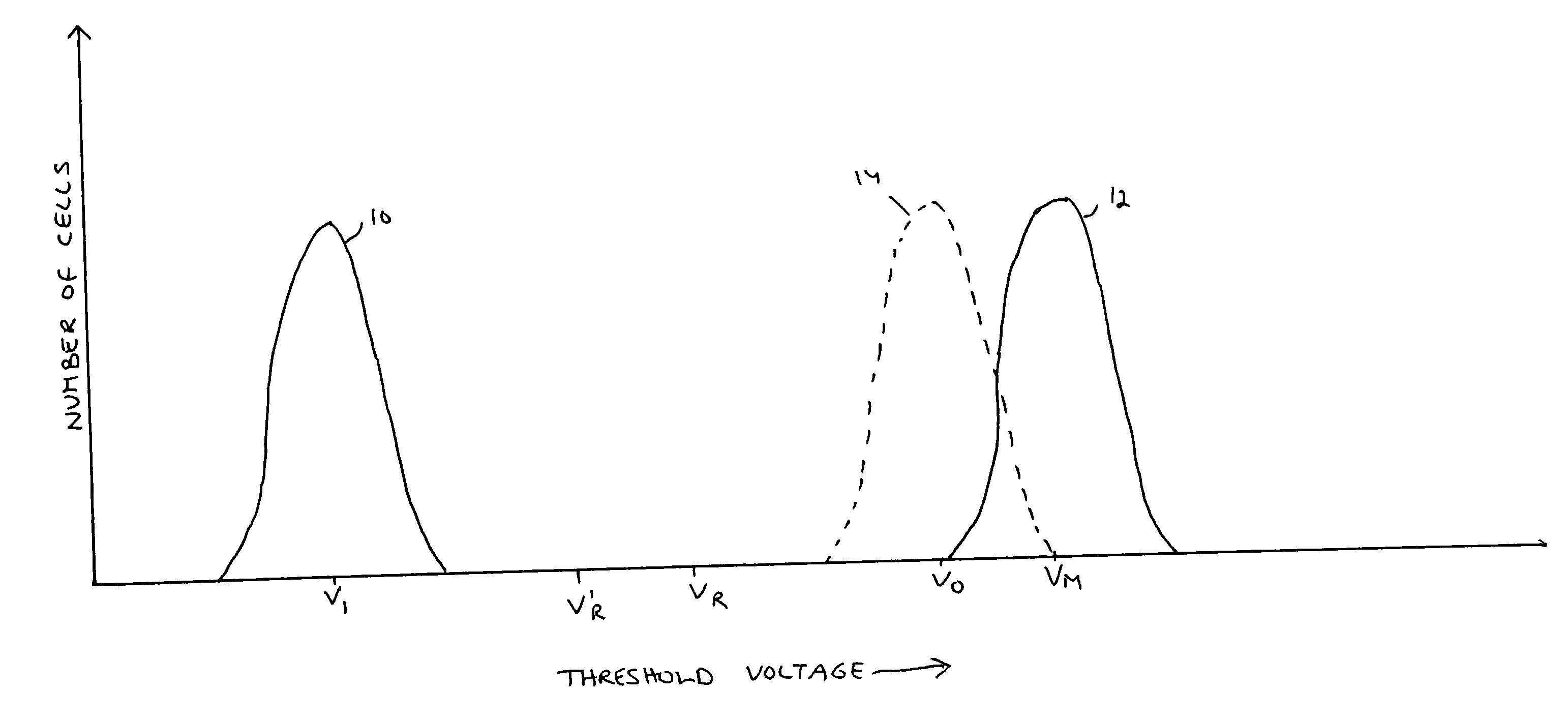
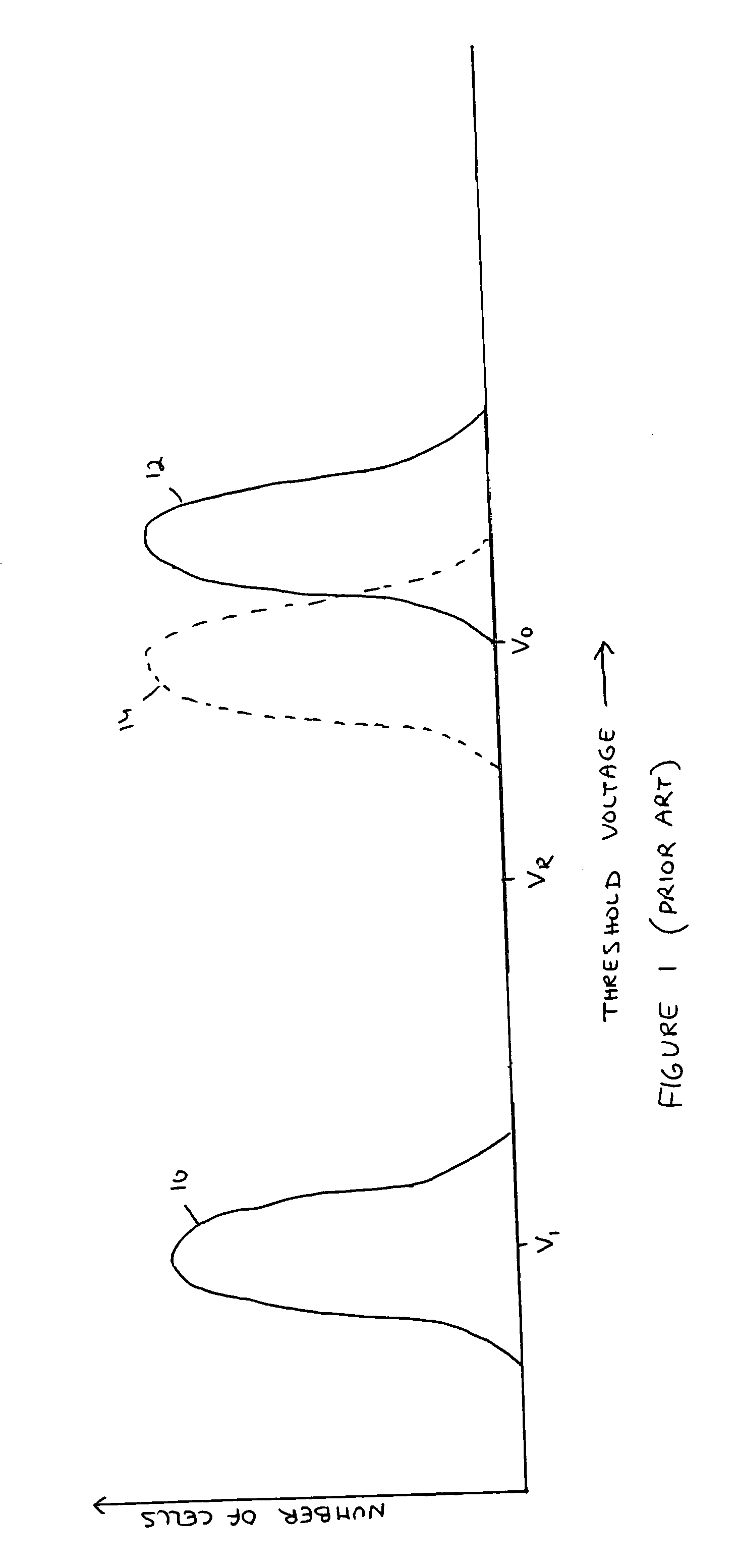
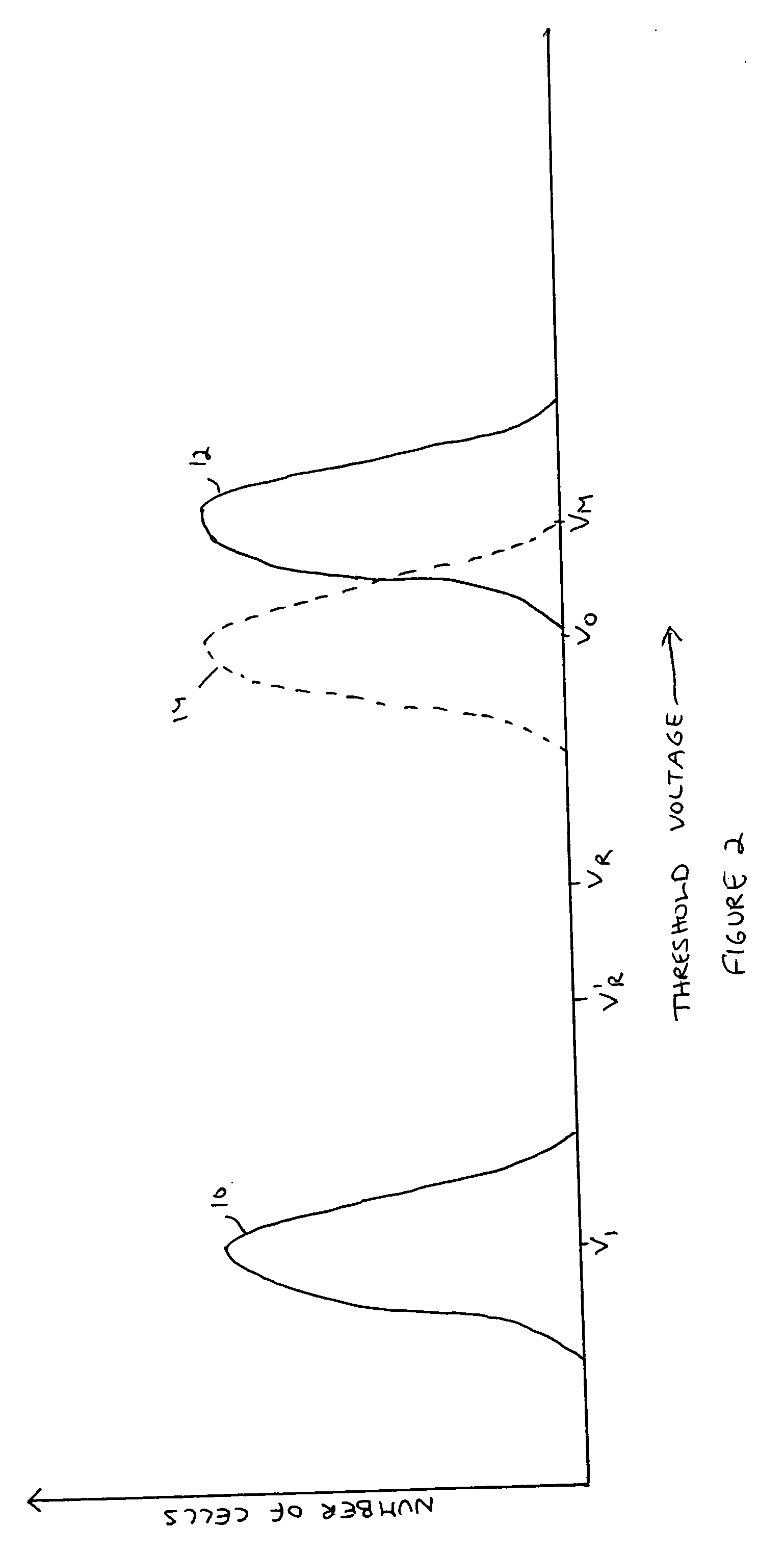
where P / E_coefficient is an empirically determined coefficient that applies to all the threshold voltage bands of the MLCs, Band_number_coefficient is an empirically determined coefficient that applies to a particular threshold voltage band (higher voltage bands are expected to drift more over time than lower voltage bands), P / E_count is the number of P / E cycles that the block has endured, P / E_initial offset is an empirically determined constant offset and Estimated drift is the amount by which the lower end of the band's threshold voltage distribution is estimated to drift downward. For example, if P / E_coefficient has been determined empirically to be 1.6×10⁻⁵V / cycle, if Band_number_coefficient for a par...

example 2

A Model that Depends on Data Retention Time but not on the Number of P / E Cycles

[0043] The model is linear in the data retention time. For a page of a MLC NAND flash memory device, the model is

Estimated—drift=Data—retention—coefficient*Band—number coefficient*Time—since—programmed+Data—retention—initial—offset.

where Data_retention_coefficient is an empirically determined coefficient that applies to all the threshold voltage bands of the MLCs, Band_number_coefficient is an empirically determined coefficient that applies to a particular threshold voltage band, Time_since_programmed is the time that has elapsed since the page was programmed, Data_retention_initial_offset is an empirically determined constant offset and Estimated_drift is the amount by which the lower end of the band's threshold voltage distribution is estimated to drift downward. For example, if Data_retention_coefficient has been determined empirically to be 0.08V / yr, if Band_number_coefficient for a particular ban...


PUM


Abstract

A plurality of memory cells are managed by obtaining values of one or more environmental parameters of the cells and adjusting values of one or more reference voltages of the cells accordingly. Alternatively, a statistic of at least some of the cells, relative to a single reference parameter that corresponds to a control parameter of the cells, is measured, and the value of the reference voltage is adjusted accordingly. Examples of environmental parameters include program-erase cycle count, data retention time and temperature. Examples of reference voltages include read reference voltages and program verify reference voltages. Examples of statistics include the fraction of cells whose threshold voltages exceed initial lower bounds or initial medians.

Description

[0001] This patent application claims the benefit of U.S. Provisional Patent Applications Nos. 60 / 624,233 and 60 / 624,234, both filed Nov. 3, 2004FIELD AND BACKGROUND OF THE INVENTION [0002] The present invention relates to the management of non-volatile memories and, more particularly, to a method of managing a memory such as a flash memory whose physical representation of the data stored therein tends to drift over time. [0003]FIG. 1 illustrates the storage of a bit, either a zero bit or a one bit, in a cell of an electrically programmable memory (EPROM) such as a flash memory. For historical reasons, this process of storing data in a EPROM is called “programming” the EPROM. Specifically, the cell that is the subject of FIG. 1 stores one bit of data, and so commonly is called a single-level cell (SLC). Initially, the cell has a nominal threshold voltage V1 that represents a one bit. For example, after a block of a flash memory has been erased, all the cells have nominal threshold v...

Claims


Application Information

Patent Timeline
Patent Type & Authority Applications(United States)
IPC IPC(8): G11C16/04
CPCG11C16/12G11C16/3459G11C16/3422G11C16/3418G11C16/34G11C16/30G11C16/10
Inventor AVRAHAM, MEIRRONEN, AMIR
Owner WESTERN DIGITAL ISRAEL LTD
Why Eureka
Try Eureka