Stator of a moineau-pump

a stator and moineau technology, applied in the direction of machines/engines, rotary/oscillating piston pump components, liquid fuel engines, etc., can solve the problem that the elastomer coating on the interior of the tube needs not to be uniform, and achieves the effect of preventing excess expansion or collapse, facilitating sealing engagement, and great rigidity and strength

Inactive Publication Date: 2006-02-09
NOETIC TECH INC
View PDF13 Cites 30 Cited by
  • Summary
  • Abstract
  • Description
  • Claims
  • Application Information

AI Technical Summary

Benefits of technology

The patent describes a method for using a thin walled stator in a pump or motor. The method involves using a coaxially positioned support housing to react the majority of the pressure differential. The support housing has internal lobes or discrete cavities that allow for a variation of fluid pressure to equalize the pressure between the stator and the support housing. The method can be used with both thick walled and thin walled embodiments, with the thin walled embodiments having the benefit of reacting a significant portion of the seal interference through non-heat generating deformation of the tube wall rather than mostly as heat generating elastomer deformation. The method also includes means to transfer radial load from the exterior of the thin walled stator to the interior of the support housing. Overall, the method provides improved performance and efficiency of the pump or motor.

Problems solved by technology

The technical problem addressed in this patent is the need to reduce heat generation and swelling in the elastomeric insert of conventional PC pumps and motors, while also allowing for close tolerance control for the stator. This is achieved by designing the elastomer with a cavity that matches the stator cavity, but requires a thin layer of elastomer to achieve the final geometry, which can be costly to manufacture.

Method used


Image

  • Stator of a moineau-pump
  • Stator of a moineau-pump
  • Stator of a moineau-pump

Examples


Embodiment Construction

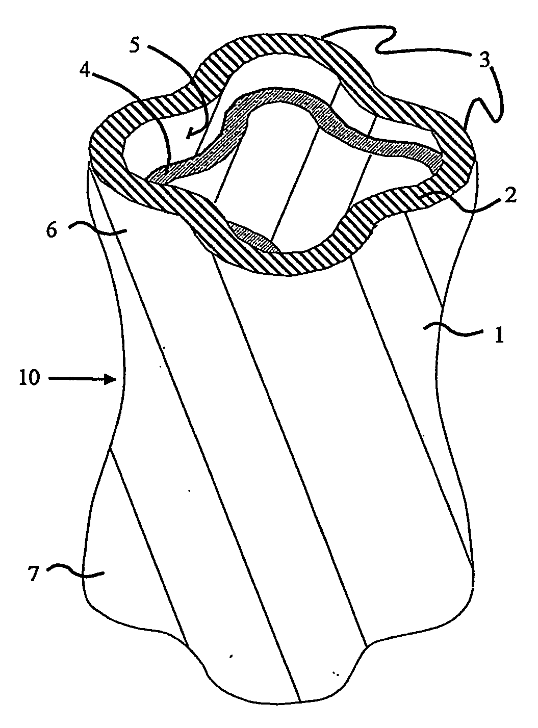
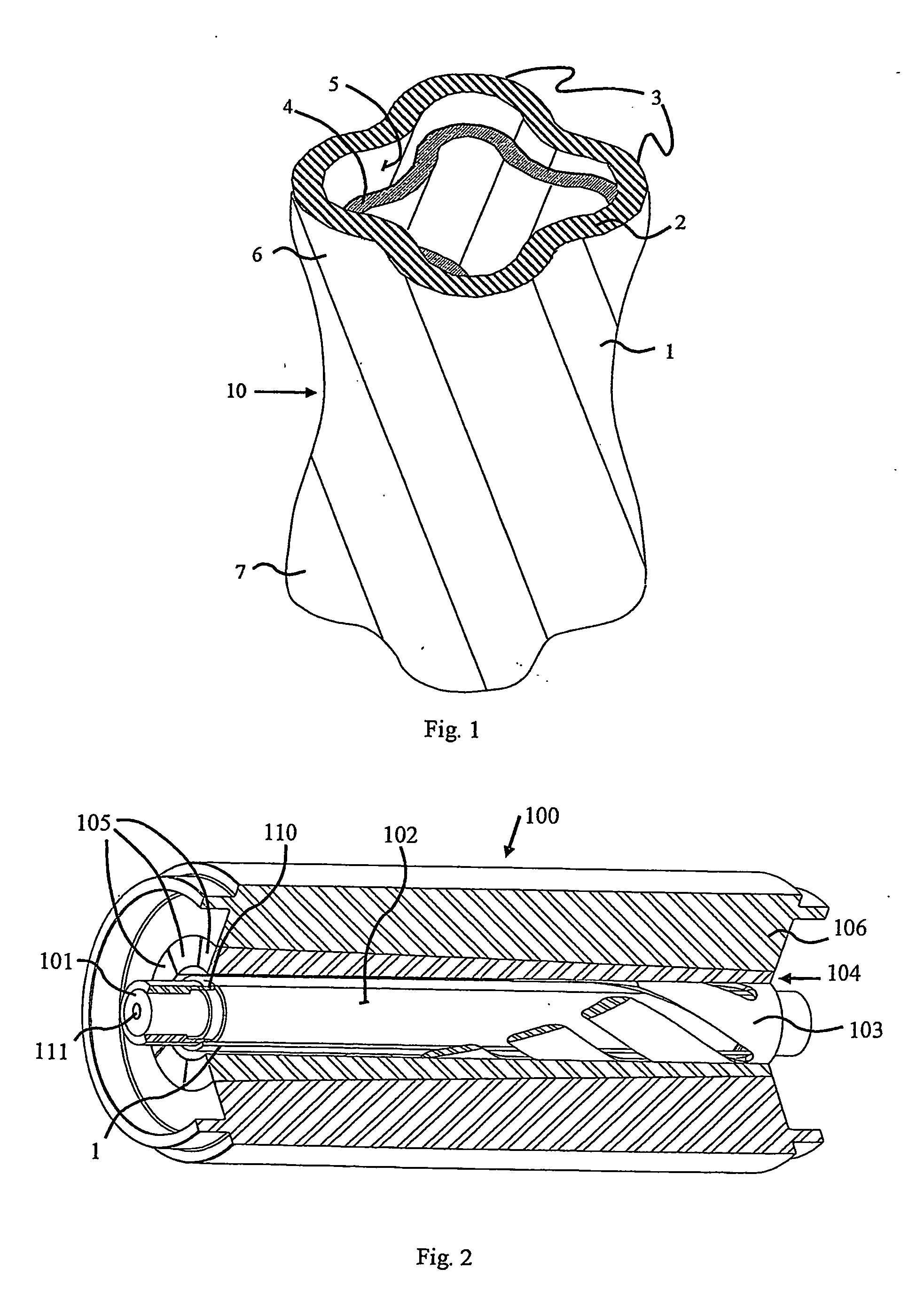
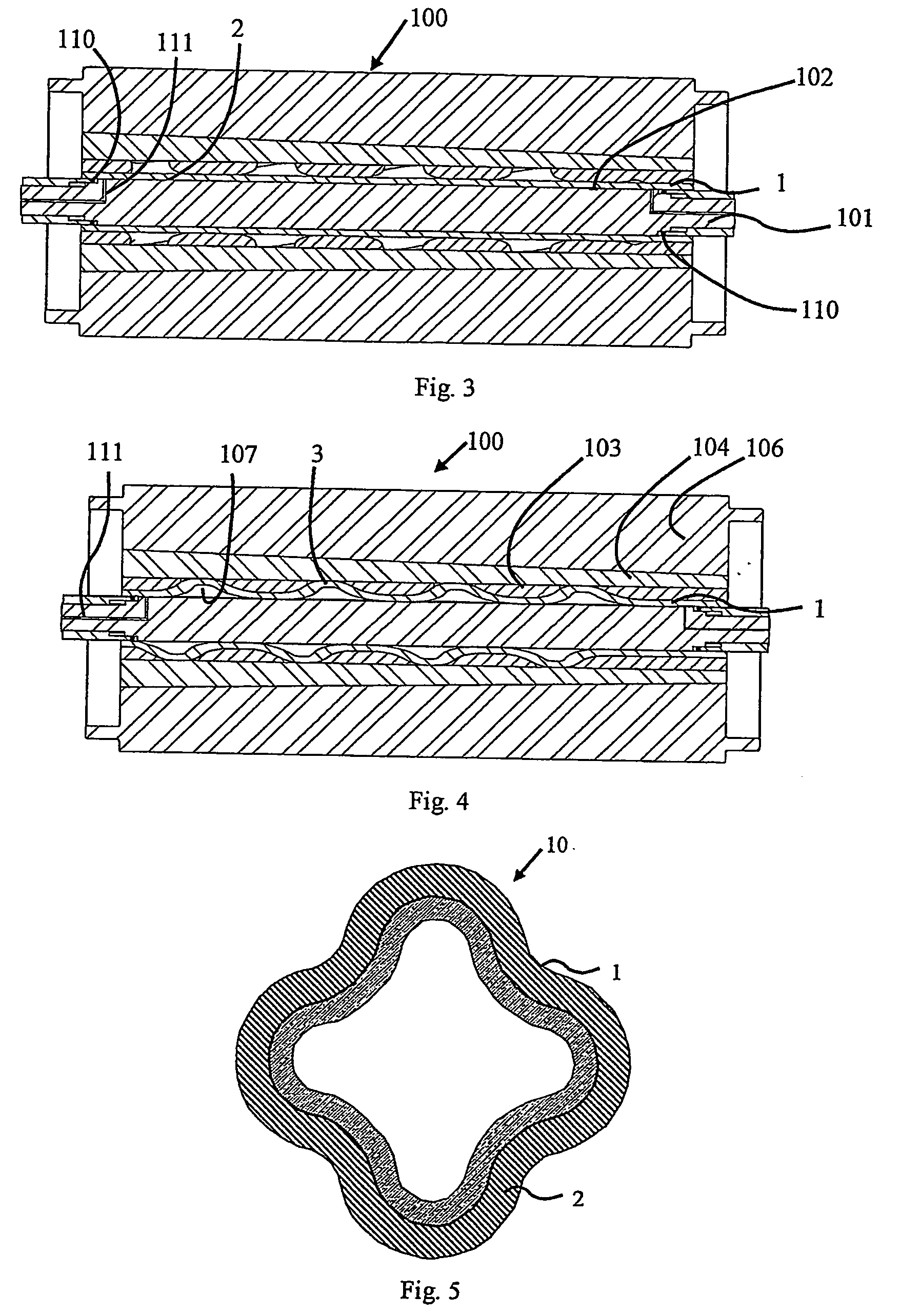
[0027] The preferred embodiment, a uniform elastomer thickness Moineau stator generally identified by reference numeral 10, will now be described with reference to FIGS. 1 through 10.

[0028] Referring now to FIG. 1, a stator 10 is shown comprised of a stator body 1 formed from a metal tube having a sidewall 2 into which a plurality of helically symmetric lobes 3 are placed, illustrated here as it would appear configured in a four lobe Moineau stator. An elastomeric liner 4 is disposed on the inside surface 5 of the stator body 1. The lobes are placed by a specialized stator hydroforming process.

[0029] Hydroforming is a manufacturing method that generally uses fluid pressure to deform a ductile metal shell against a mold. To form shapes such as required for stators 10, the mold can take a number of helical and solid forms, configured so that the post-hydroformed internal profile of the stator housing obtains the general form of the lobed profile of the inner surface of the elastomer...


PUM

PropertyMeasurementUnit
Currentaaaaaaaaaa
Lengthaaaaaaaaaa
Thicknessaaaaaaaaaa

Abstract

A Moineau stator includes a tube (10) having lobes (3) arranged in a configuration which is adapted to interact with a rotor and formed through a hydroforming process.

Description


Claims


Application Information

Patent Timeline
Owner NOETIC TECH INC
Why Eureka
Try Eureka