Support with removable pressure/alignment ring

Active Publication Date: 2006-02-09
NORDT DEVMENT
View PDF99 Cites 79 Cited by
  • Summary
  • Abstract
  • Description
  • Claims
  • Application Information

AI Technical Summary

Benefits of technology

[0010] In another feature of this aspect, openings in the surface of the framework do not extend entirely through the framework, thereby forming cavities in the surface. Alternatively, the surface in which the openings are defined comprises an inner surface of the support for disposition toward the body, and the openings extend completely through the framework to an outer surface of the framework. A benefit of the openings extending from inner to outer surfaces of the framework is that these openings may permit portions of the area of the body that are in abutting engagement with the framework to breathe, especially where the inner surface directly contacts the body and no intermediate member extends there between, such as a liner. The area of the openings in the surface of the framework to the surface area of the framework preferably has an “open air ratio” of 50% or greater.

Problems solved by technology

Such joint ailments often can be attributed to damages and degenerative wear in the contact surfaces of bone ends meeting at the joint.

Method used


Image

  • Support with removable pressure/alignment ring
  • Support with removable pressure/alignment ring
  • Support with removable pressure/alignment ring

Examples


first embodiment

a Support

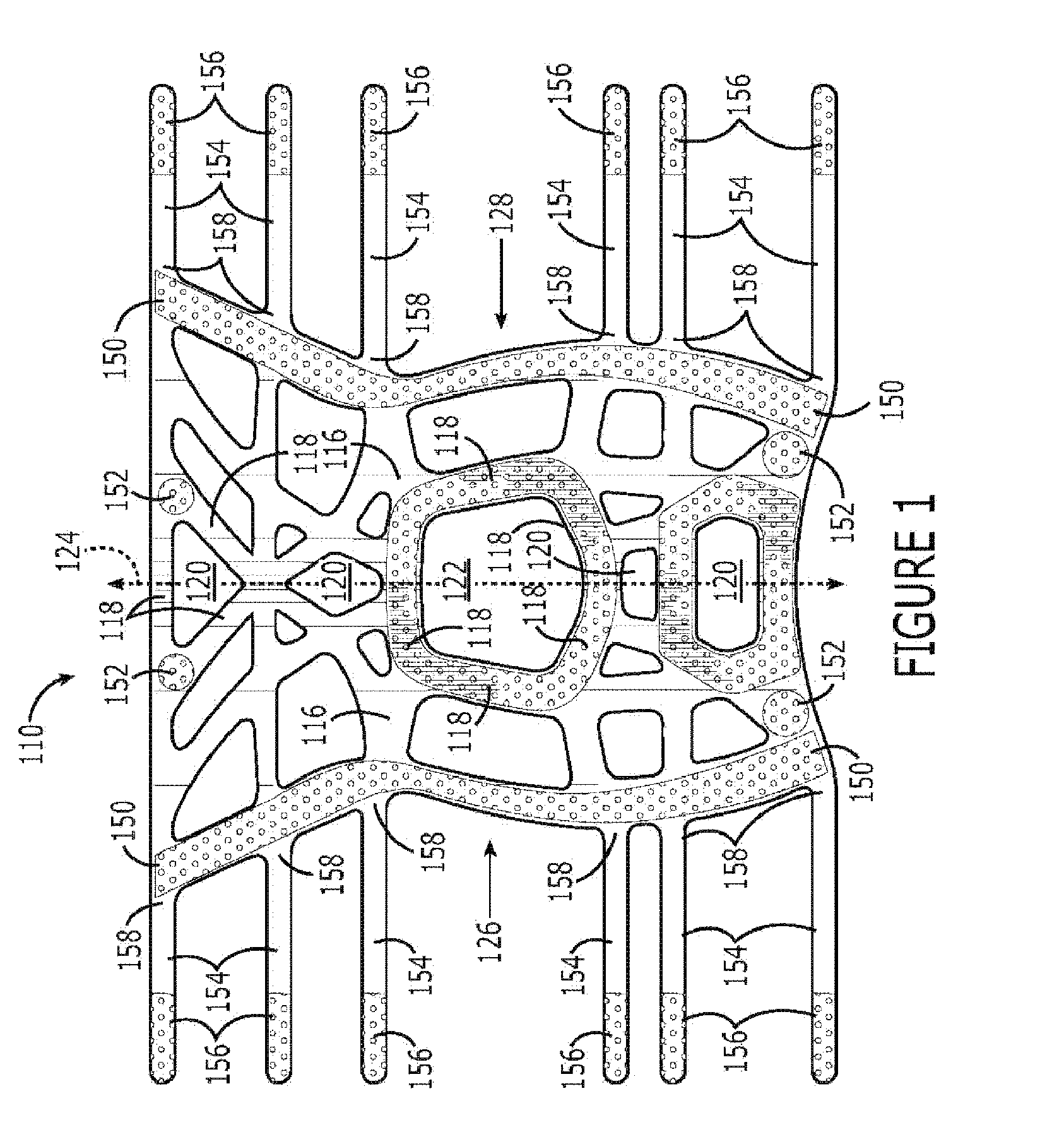
[0123] With regard to the first embodiment of a support for an area of a body, a flexible and elastically stretchable framework 110 thereof is shown in FIG. 1. The framework 110 comprises generally linear segments or members 118 interconnected to define a plurality of permanent openings 120 that extend completely through the framework. Furthermore, some of these openings 120 are completely bounded by the interconnected members 118, and the interconnected members 118 defining such an opening constitute a portion of the framework 110 that is stretchable and recoverable about the entire boundary of the opening with the framework 110. Moreover, the openings 120 are permanent and exist regardless of whether the framework 110 actually is disposed in abutment with the body due to the permanent interconnection of the members 118 defining the openings 120. The framework 110 preferably is formed from an elastomeric material in a conventional molding process and, in this particular em...

second embodiment

a Support

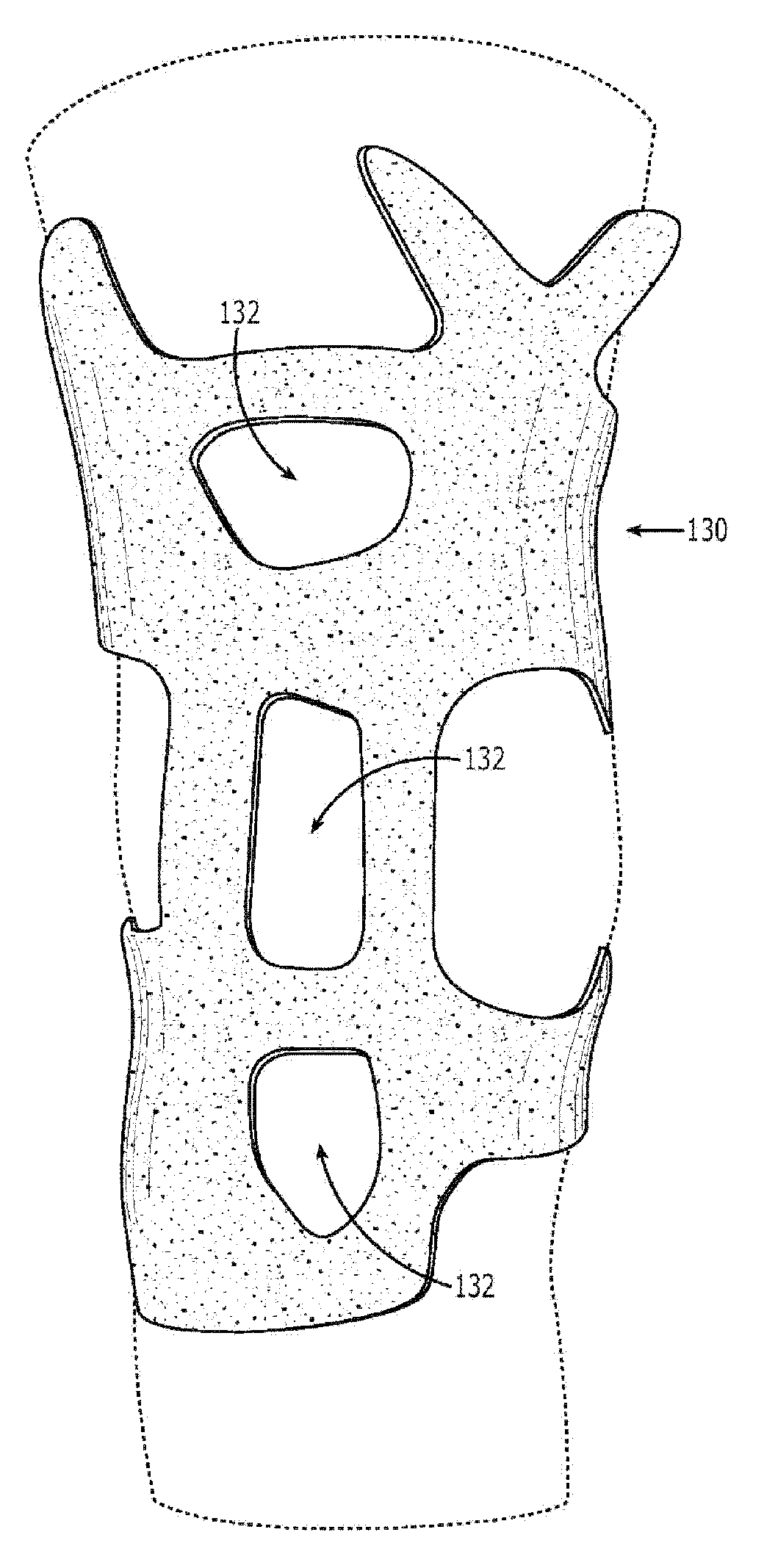
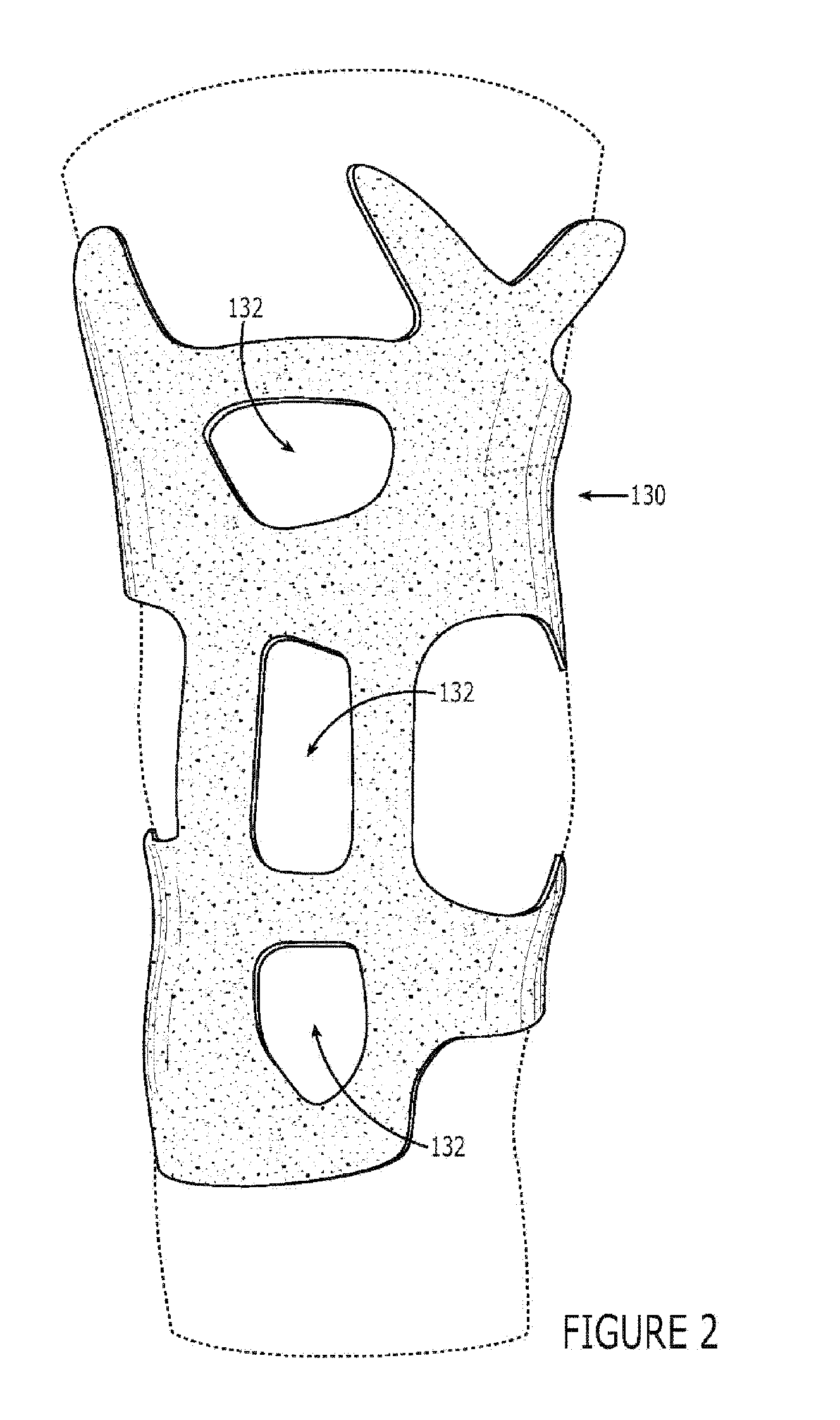
[0136] With regard to the second embodiment 2000 of a support for an area of a body, the second embodiment 2000 includes a framework that is the same as the framework 110 of the first embodiment 1000. The second embodiment 2000 further is considered to include, as part thereof, sleeve 168 (FIGS. 7-8) that is generally the same as sleeve 130 of FIGS. 2-3, except that the sleeve 168 is continuous and does not define openings therein that would register with corresponding openings of the framework 110. As shown in FIG. 7, sleeve 168 includes fasteners covering most of the entire outer surface of the sleeve. Alternatively, as shown in FIG. 8, the sleeve 168 includes certain discrete areas 172 that comprise loop fasteners for receiving the hook fasteners 156 of fastening straps 154 (FIG. 1) and, thus, does not include loop fasteners covering most of the entire outer surface of the sleeve as shown in FIG. 7. FIG. 9 illustrates the second embodiment 2000 including the framework 11...

third embodiment

a Support

[0137] The third embodiment 3000 of a support is shown in FIGS. 10-17 and is the same as the first embodiment 1000 except for the following noted differences.

[0138] First, the embodiment 3000 includes a liner 198 (FIG. 16) that is attached directly to the framework 182 such as, for example, by plasticized welding, elastomeric welding, adhesive attachment, or by sewing. The support further includes two bands 199a,199b (FIG. 16) extending between and directly attached to the two opposite sides of the framework 182.

[0139] Second, the fastening mechanism includes four fastening components, each of which comprises a claw member 196 that is removable from (FIG. 10) and attachable to (FIG. 16) the framework 182. As shown in FIG. 10, each claw member 196 includes a number of fastening belts 200 joined by a fastening pad 202. First faces 204 of the claw members 196 have adjustment-fasteners 206 attached to the fastening belts 200 as shown in FIG. 10. The adjustment-fasteners 206 a...


PUM


Abstract

A support for an area of a body including a hinge joint includes: a framework having a surface for abutment with an area of a body including a hinge joint, said framework defining a permanent opening in said surface regardless of whether said surface is in abutment with the area of the body, said permanent opening extending completely through said framework; and a member removable from said framework that is positionable proximate to said permanent opening of said framework for disposition between said permanent opening of said framework and the area of the body to be supported, said removable member being contoured to receive therein a joint protuberance of the hinge joint.

Description

CROSS-REFERENCE TO RELATED APPLICATIONS [0001] The present application is a continuation-in-part patent application of U.S. nonprovisional patent application Ser. No. 11 / 058,109 filed Feb. 15, 2005, which is incorporated herein by reference. The present application also is a nonprovisional patent application of, and claims priority under 35 U.S.C. § 119(e) to each of: U.S. provisional patent application Ser. No. 60 / 590,852, filed Jul. 22, 2004, which is incorporated herein by reference; U.S. provisional patent application Ser. No. 60 / 590,946, filed Jul. 22, 2004, which is incorporated herein by reference; and U.S. provisional patent application Ser. No. 60 / 637,026, filed Dec. 17, 2004, which is incorporated herein by reference.COPYRIGHT STATEMENT [0002] All of the material in this patent document is subject to copyright protection under the copyright laws of the United States and other countries. The copyright owner has no objection to the facsimile reproduction by anyone of the pat...

Claims


Application Information

Patent Timeline
IPC IPC(8): A61F5/00
CPCA41D13/05A61F5/0106A41D13/08A41D13/065A61F5/0118
Inventor NORDT, WILLIAM E. IIIKOVACEVICH, IAN D.DAHLQUIST, KEVIN J.PHILPOTT, TOM J.
Owner NORDT DEVMENT
Why Eureka
Try Eureka