Device for catching insects

Inactive Publication Date: 2006-02-16
GEORGE DAVID MICHAEL +1
View PDF42 Cites 12 Cited by
  • Summary
  • Abstract
  • Description
  • Claims
  • Application Information

AI Technical Summary

Benefits of technology

[0003] In accordance with the present invention, there is provided a versatile and easy to use device for catching insects in a variety of settings. The device comprises an elongated member having a first and a second distal portion. An insect trapping head is mounted on the first distal portion and includes a first member and a second member pivotally mounted with respect to each other, preferably by a spring hinge. The first and second members are moveable between one of an open or closed position and the other of an open or closed position by an actuating mechanism. Preferably, the actuating mechanism is disposed on the second distal portion of elongated member. When using a spring hinge to connect the first and second members, the members typically open from a closed position to an open position with respect to one another through engagement of the actuating mechanism and thereafter rapidly return to the closed position. When in the closed position, the first and second members collectively define a rigid compartment such that one or more insects can be trapped between the first and second members. Typically, to permanently maintain the trapped insects in the rigid compartment, the device also includes a sticky surface on at least a portion of the interior of the compartment.
[0008] In accordance with another aspect of the present invention, engagement of the actuating mechanism of the device opens one of the first and second members from about 0 to about 340 degrees relative to the other member, and preferably to about 270 degrees relative to the other member. The spring hinge thereafter enables the first and second members to thereafter rapidly close with respect to one another. Typically, the actuating mechanism includes a trigger mechanism which is disposed on the second distal portion of the elongated member. The trigger mechanism may be of any shape such that the trigger mechanism is easily engageable by the thumb and / or fingers of the user. In one embodiment, at least a portion of the trigger mechanism is disposed within a recess which extends longitudinally within at least a portion of the elongated member adjacent a handle on the second distal portion.
[0010] In another embodiment, the actuating mechanism includes a slider mechanism disposed on the second distal portion of the elongated member which when moved rearward by a user causes one of the first and second members to move from a closed position to an open position with respect to the other member. The spring hinge enables the members to rapidly return to the closed position after being opened by actuation of the slider mechanism. The slider mechanism may include a knob and a male member. The knob is engageable by the thumb or fingers of the user and the male member extends into a bore of the elongated member. The bore includes a groove, which is preferably angled, in which the male member can be selectively maintained within to fix the first and second members in the open position as desired, preferably with second member opened to about 270 degrees with respect to first member. To return the first and second members to a closed position, the male member can be moved in an upward direction out of the groove and back into the bore of the elongated member.
[0012] In accordance with another aspect of the present invention, a body of one or both of the first and second members includes a plurality of air holes, preferably around a perimeter on the rear side of the member(s), to decrease air resistance when the device is used. Alternatively, at least one of the first and second members may include a screened portion also to decrease air resistance to the device when in use. Additionally, the top edge of a perimeter of at least one of the first and second members may include a rubber portion to protect the edges of the members and to protect walls or other surfaces when the members are in contact with such surfaces. Further, the top edge of a perimeter of at least one of the first and second members may include a plurality of bristles to enable the member(s) to be used to sweep debris away from a surface as desired.

Problems solved by technology

Such pests often make individuals feel uncomfortable and may even be hazardous to certain individuals.
Conventional fly swatters are often ineffective in catching or killing insects because the norm is to wait endlessly for the insect to land on a planar surface, such as a window, wall, or table before attacking the pest.
As a result, the killing of an insect or insects using known devices leaves an unsightly and unsanitary residue on either or both of the device and the killing surface.
This cleaning step is inefficient, unpleasant, and can also be especially dangerous when dealing with stinging insects.

Method used


Image

  • Device for catching insects
  • Device for catching insects
  • Device for catching insects

Examples


Embodiment Construction

[0025] While this invention is susceptible of embodiment in many different forms, there is shown in the drawings and described in detail herein, several specific embodiments with the understanding that the present disclosure is to be considered as exemplifications of the principles of the invention and is not intended to limit the invention to the embodiments illustrated.

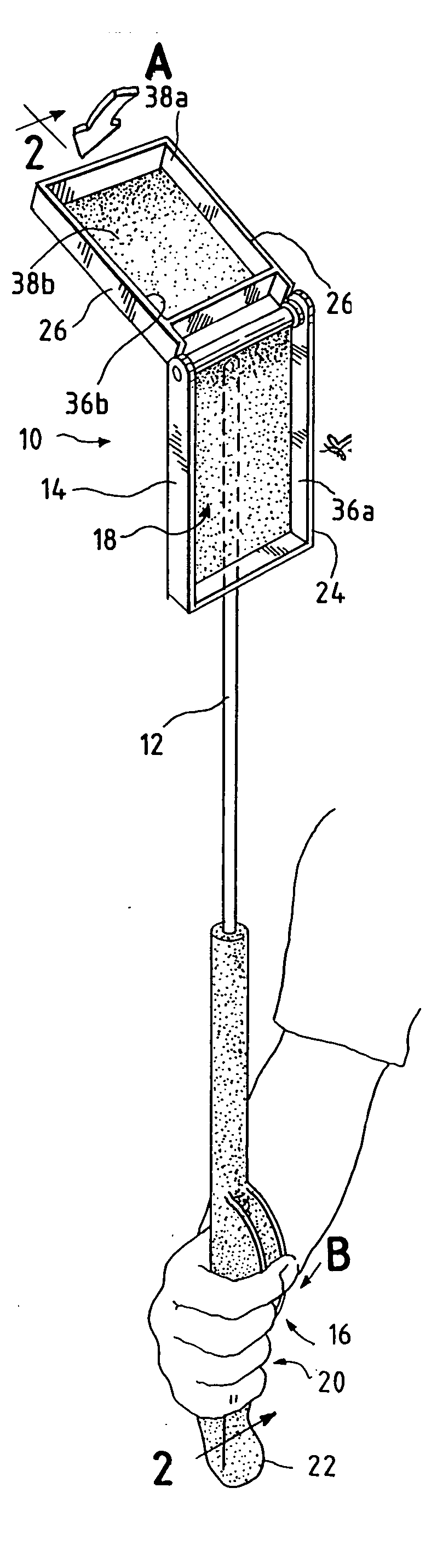
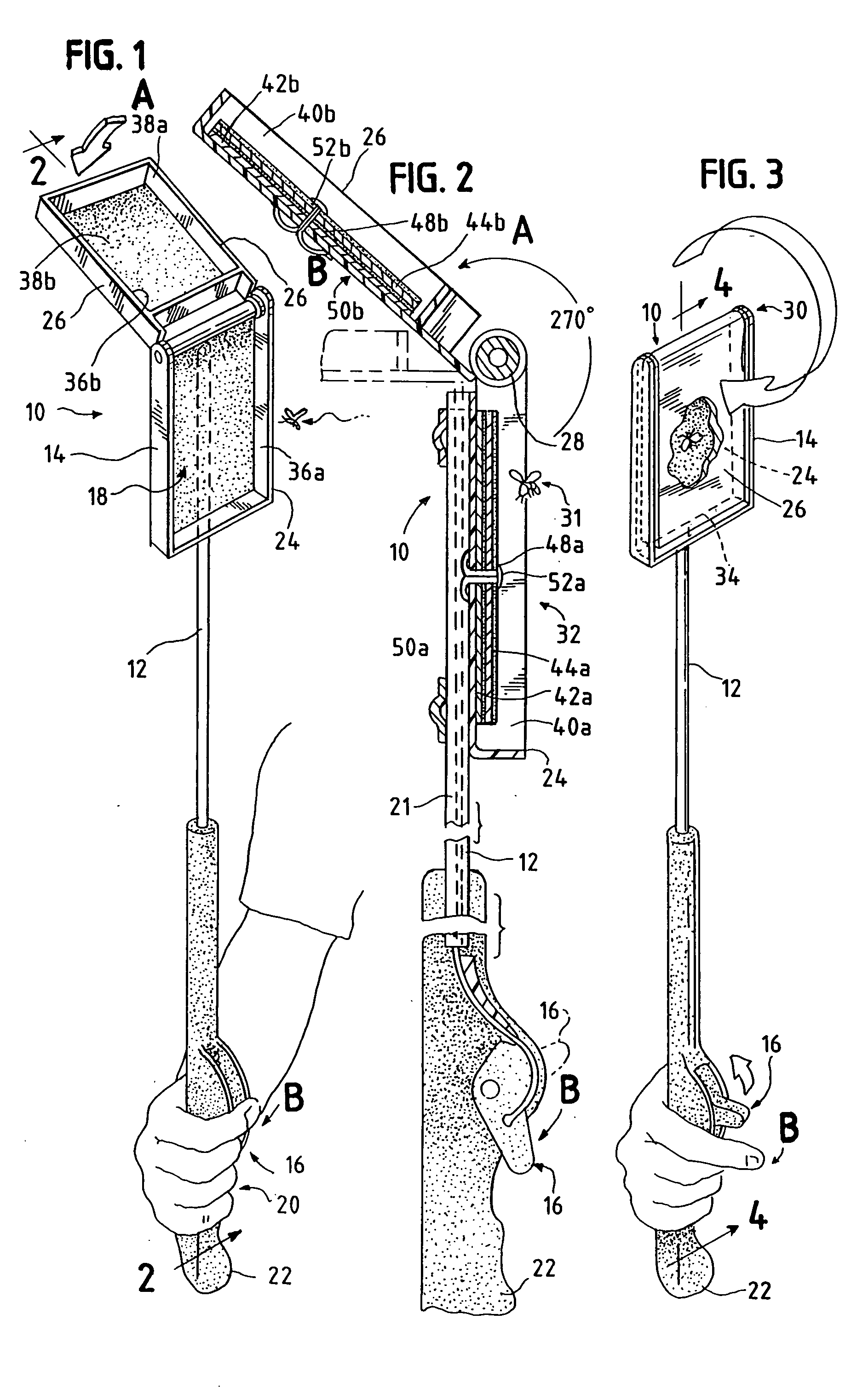
[0026] Now referring to the drawings, a device 10 for catching insects in accordance with the present invention is shown generally in FIG. 1 as including an elongated member 12, an insect trapping head 14, and an actuating mechanism 16. Elongated member 12 has a first distal portion 18 and a second distal portion 20. Typically, as shown in FIG. 2, elongated member 12 comprises an elongated rod having a bore 21. Elongated member 12 may be formed from aluminum, steel, durable plastic, or any other relatively rigid material, and is preferably about 24 inches in length. Preferably, elongated member 12 includes a handle...


PUM


Abstract

A device for catching insects is provided which includes an elongated member with first and second distal portions, an insect trapping head mounted on the first distal portion, and an actuating mechanism. The insect trapping head includes a first member and a second member pivotally mounted with respect to each other such that one of the members is moveable from about 0 to about 340 degrees relative to the other member, and preferably to about 270 degrees relative to the other member by activation of the actuating mechanism. When in the closed position, the first and second members define a rigid compartment such that the insect can be trapped between the first and second members. Preferably, a sticky surface on at least a portion of the interior of the compartment maintains the insects within the compartment.

Description

FIELD OF THE INVENTION [0001] The present invention relates to an improved device for catching and trapping insects in flight or resting on a surface. BACKGROUND OF THE INVENTION [0002] Bees, hornets, fruit flies, mosquitoes and numerous other insects can be a nuisance in any outdoor or indoor setting. Such pests often make individuals feel uncomfortable and may even be hazardous to certain individuals. Conventional fly swatters are often ineffective in catching or killing insects because the norm is to wait endlessly for the insect to land on a planar surface, such as a window, wall, or table before attacking the pest. Further, known fly swatters and other known insect catching devices require one to kill the insect by smashing the insect against the surface or by crushing the insect within the device. As a result, the killing of an insect or insects using known devices leaves an unsightly and unsanitary residue on either or both of the device and the killing surface. The user is t...

Claims


Application Information

Patent Timeline
IPC IPC(8): A01M3/04A01M1/14
CPCA01M3/022A01M2200/012A01M3/04
Inventor GEORGE, DAVID MICHAELJOHNSON, RYAN BRUCE
Owner GEORGE DAVID MICHAEL
Why Eureka
Try Eureka