Polarized optical elements enhancing color contrast and methods for their manufacture

a technology of color contrast and optical elements, applied in the field of polarized optical elements, can solve the problems of conventional optical elements, sunglass lenses, and inability to effectively reduce the effects of glare, and achieve the effects of enhancing visual acuity, reducing glare, and increasing red sensitivity

Inactive Publication Date: 2006-02-16
INTERCAST EURO
View PDF5 Cites 49 Cited by
  • Summary
  • Abstract
  • Description
  • Claims
  • Application Information

AI Technical Summary

Benefits of technology

The present invention aims to provide an optical element that reduces glare and eye fatigue when wearing high-intensity reflected light. It also improves visual acuity, especially for red and blue colors.

Problems solved by technology

The technical problem addressed in this patent text is the need for a polarized optical element that reduces glare without compromising visual acuity, especially when driving. The existing polarized optical elements can distort color vision and fail to meet the standards for traffic and color recognition. Additionally, the use of certain rare earth oxides can be problematic due to their absorption of light in the tunnels and road signals.

Method used


Image

  • Polarized optical elements enhancing color contrast and methods for their manufacture
  • Polarized optical elements enhancing color contrast and methods for their manufacture
  • Polarized optical elements enhancing color contrast and methods for their manufacture

Examples


example 1

(Prior Art)

[0165] A polarized lens made of diethylenglycol-bis-allyl-carbonate (CR39®) was obtained by means of a casting method comprising placing a polarizing disc made of a polyvinylalcohol film 30 microns thick (Kurarai, JP) preformed to have a substantially spherical surface in a cavity formed by molds having concave and convex inner surfaces. A solution of transparent polymerizable diethylenglycol-bis-allyl-carbonate monomer including 3% of cross-linking catalyst (diisopropyl peroxy dicarbonate) and 0.3% of UV absorber Uvinul® 3049 (BASF) was then poured on opposite sides of the polarizing film and then polymerized. The polymerization cycle lasted 20 hours and the temperature was adjusted between 40° and 80° C. according to polymerization procedures well known to those skilled in the art.

[0166] The polarized lens thus obtained was dyed by means of a thermal transfer technique in liquid phase. To this end, a dyeing bath was prepared comprising an aqueous solution including: 0...

example 2

(Prior Art)

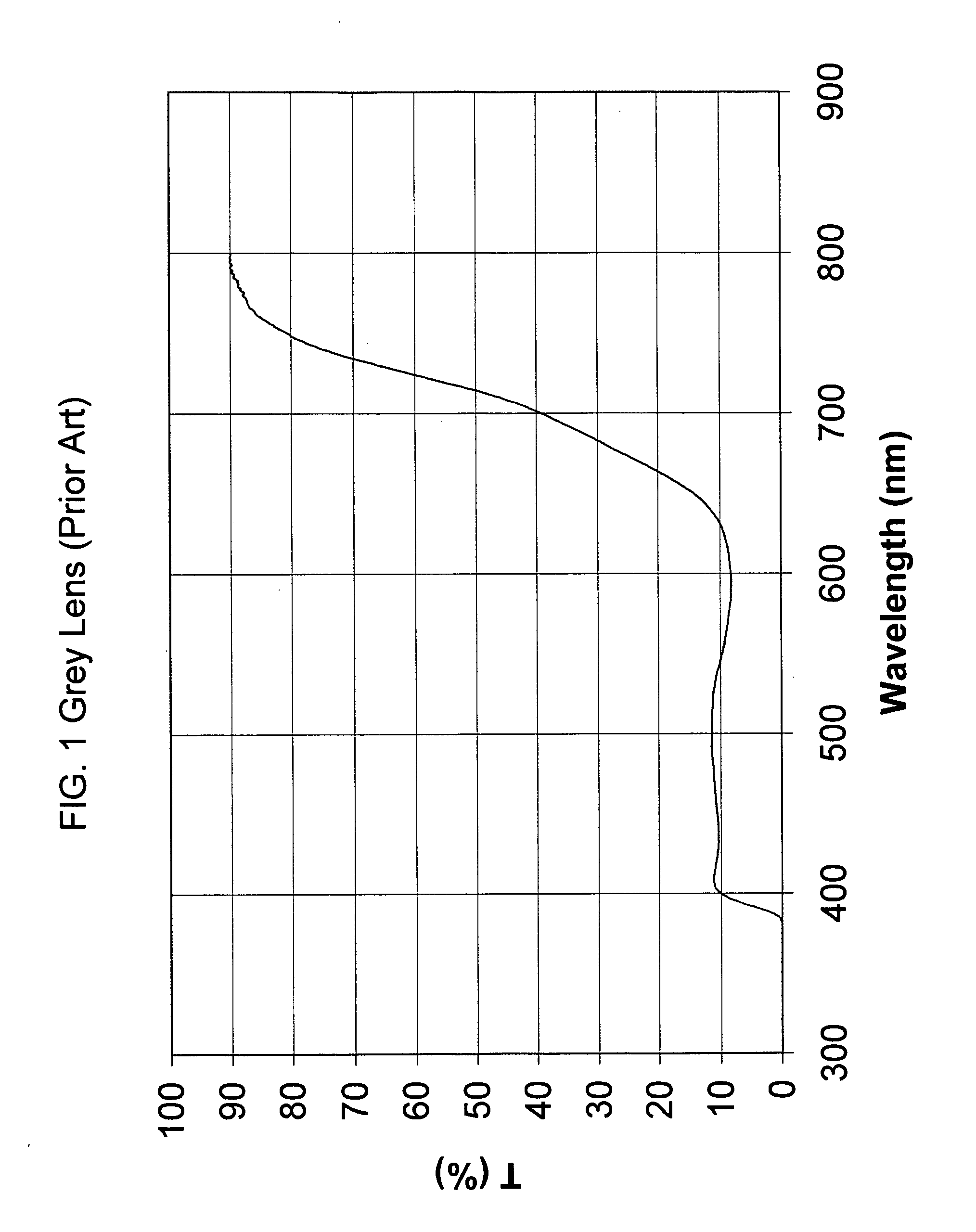
[0168] A polarized lens was manufactured by injection molding of a polycarbonate resin onto a polarizing curved disc made of a polyvinylalcohol (PVA) film sandwiched between two layers of polycarbonate. The total thickness of the film is 0.4 mm. The resin was dyed in bulk by incorporating the following Soluble dyes: 0,020% Solvent Blue 128, 0.015% Solvent Red 52, 0.01% Solvent Yellow 114. 0.2% of Tinuvin 326 (CIBA) as UV absorber was also incorporated into the resin.

[0169] The curve of spectral transmittance obtained is the curve of a brown lens and is shown in FIG. 2.

example 3

(Prior Art)

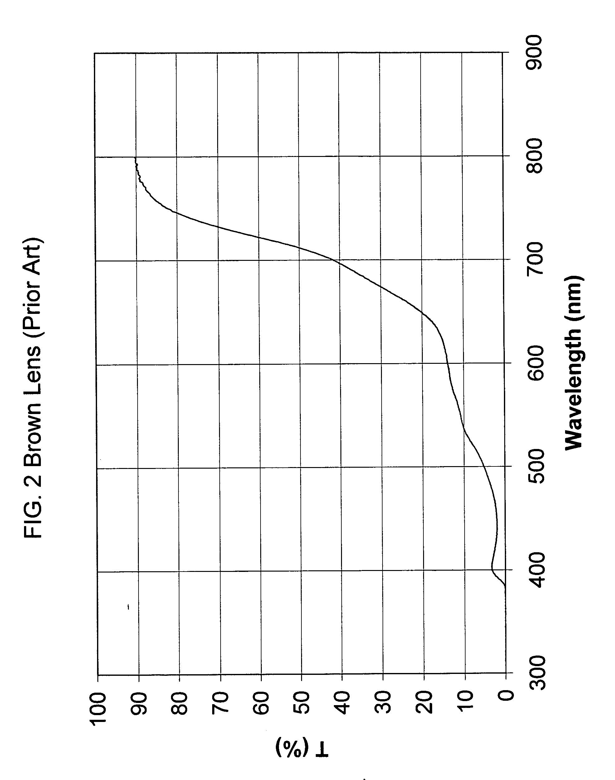
[0170] A polarized lens was manufactured by bonding at a temperature of 90° C. and at a pressure of 7 bar in an autoclave a polyamide lens made by Trogamid® (Degussa) dyed in bulk with the same Soluble dyes of the Example 2 onto a curved disc of polarizing film made of PVA bonded onto a layer of Cellulose Triacetate film.

[0171] The curve of spectral transmittance obtained is the curve of a copper lens and is shown in FIG. 3.


PUM


Abstract

A polarized optical element comprising a polarized optical part is dyed so that the optical part exhibits a curve of spectral transmittance in a wavelength range comprised between 400 and 700 nm comprising: i) at least one relative maximum at a wavelength comprised between 400 and 510 nm, and ii) at least one relative minimum at a wavelength comprised between 510 to 625 nm, wherein the ratio between the value of the factor of spectral transmittance at said at least one relative maximum and the value of the factor of spectral transmittance at said at least one relative minimum is of at least 1.3, and wherein the ratio between the value of the factor of spectral transmittance at a wavelength of 700 nm and the value of the factor of spectral transmittance at said at least one relative minimum is of at least 3.0. Advantageously, such a polarized optical element is both polarized to reduce glare and provides the wearer with enhanced visual acuity, especially an increased sensitivity to the red and blue colors so as to meet the color and traffic signal recognition requirements of the international standards.

Description


Claims


Application Information

Patent Timeline
Owner INTERCAST EURO
Why Eureka
Try Eureka