Inter-fabric routing

Inactive Publication Date: 2006-02-16
AVAGO TECH INT SALES PTE LTD
View PDF34 Cites 232 Cited by
  • Summary
  • Abstract
  • Description
  • Claims
  • Application Information

AI Technical Summary

Benefits of technology

[0024] To allow more complicated routing, the present invention proposes an inter-fabric routing header. This routing header is not needed when a single router connects multiple fabrics, or where a link between two routers does not require routing. However, the routing header does provide mechanisms to detect stale frames, prioritize frames, and to detect routing loops. To ensure that frames having a router header can pass through legacy fabrics, the present invention proposes the use of an encapsulation header.
[0025] Certain link service messages require special handling in the context of inter-fabric Fibre Channel communications. These original link service frames can be detected by examining the R_CTRL value and th

Problems solved by technology

Unfortunately, this type of zoning is meaningless if the devices are ever physically moved from one port on a switch to another.
Although this is a large number of switches for most circumstances, this limit requires the physical separation of one fabric from another.
It would not be possible to create a world-wide storage area network similar to the Internet given a limitation o

Method used


Image

  • Inter-fabric routing
  • Inter-fabric routing
  • Inter-fabric routing

Examples


Embodiment Construction

Local Inter-Fabric Routing

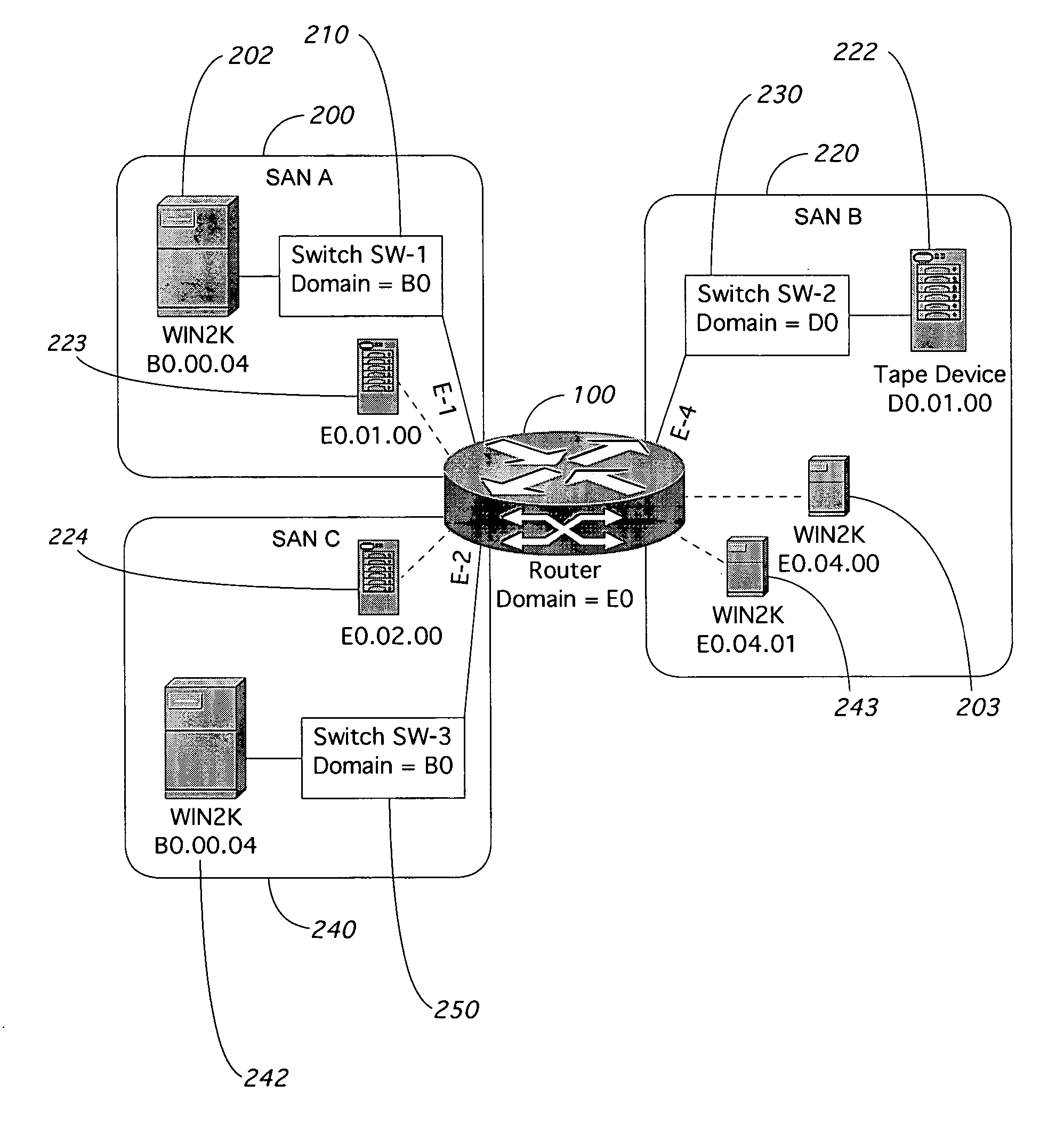
[0052] The present invention allows devices in different Fibre Channel fabrics to communicate with one another. An example of such communication is shown in FIG. 5, where a router 100 of the present invention is being used to link together three separate Fibre Channel fabrics or SANs, namely SAN A 200, SAN B 220, and SAN C 240. Inside of SAN A 200 is a switch 210 labeled Switch SW-1. This switch 210 is connected to the router 100 with what the switch 210 views as a standard interswitch link through an E-Port. This connection allows SAN A 200 to treat the router 100 as simply another switch within SAN A 200. Connected to switch SW-1210 is a Windows server 202. Switch 210 has been assigned domain B0, with the Windows server 202 being assigned a port identifier of ‘B0 00 04.’ Similarly, inside SAN B 220 is switch SW-2230, which has been assigned domain D0. Attached to switch 230 is a tape device 222, which has a Fibre Channel address of ‘D0 00 00.’ Finally, ...


PUM


Abstract

A method and apparatus is shown for communicating Fibre Channel frames between distinct fabrics. A proxy zone is established in each fabric with a physically present local device and a remote fabric device. A router creates a proxy device in each fabric for every device not physically connected to the fabric. The proxy devices appear to be directly attached to the router. The router handles all address translations between proxy and physical addresses. When multiple routers are encountered, the ingress router does all address translation. No routing or encapsulation headers are used except when routing between two routers. The source ID and the originator exchange identifier are stored at the egress router for all link requests that require special handling. When replies pass through that router, the destination ID and originator exchange identifier are compared with the stored information. On a match, the reply is specially handled.

Description

PRIORITY [0001] This application claims the benefit of U.S. Provisional Patent Application No. 60 / 589,099, filed Jul. 19, 2004.FIELD OF THE INVENTION [0002] The invention presented in this application pertains generally to the routing of information between remote devices. More particularly, the present invention relates to the routing of Fibre Channel frames between separate Fibre Channel fabrics. BACKGROUND OF THE INVENTION [0003] Fibre Channel is a switched communications protocol that allows concurrent communication among servers, workstations, storage devices, peripherals, and other computing devices. Fibre Channel can be considered a channel-network hybrid, containing enough network features to provide the needed connectivity, distance, and protocol multiplexing, and enough channel features to retain simplicity, repeatable performance, and reliable delivery. Fibre Channel is capable of full-duplex transmission of frames at rates extending from 1 Gbps (gigabits per second) to 1...

Claims


Application Information

Patent Timeline
IPC IPC(8): H04L12/56
CPCH04L45/04H04L49/357H04L49/3009
Inventor PETERSON, DAVID
Owner AVAGO TECH INT SALES PTE LTD
Why Eureka
Try Eureka