Multi-function two panel electronic device with 360° relative motion

Inactive Publication Date: 2006-02-16
NOKIA CORP
View PDF40 Cites 65 Cited by
  • Summary
  • Abstract
  • Description
  • Claims
  • Application Information

AI Technical Summary

Benefits of technology

[0026] In another aspect of this invention, operation of the camera includes an attracter mode. In this mode the touch sensitive display is configured to prov

Problems solved by technology

With the introduction of multi-function electronic devices, it has become increasingly more difficult to design a user interface that enables the user to access the many types of functions and applications available in sma

Method used


Image

  • Multi-function two panel electronic device with 360° relative motion
  • Multi-function two panel electronic device with 360° relative motion
  • Multi-function two panel electronic device with 360° relative motion

Examples


embodiment

An Alternate Embodiment

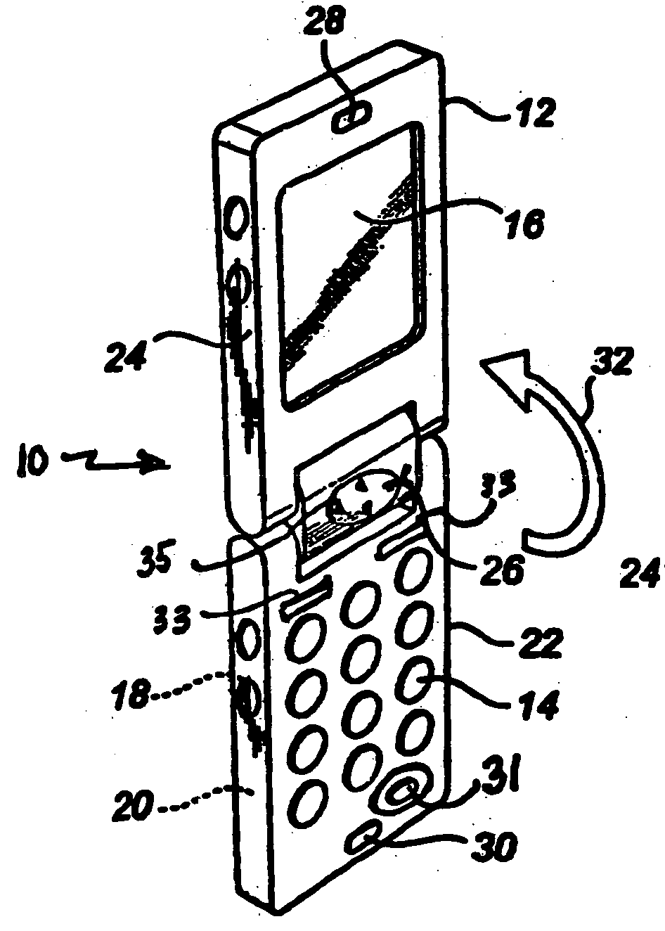
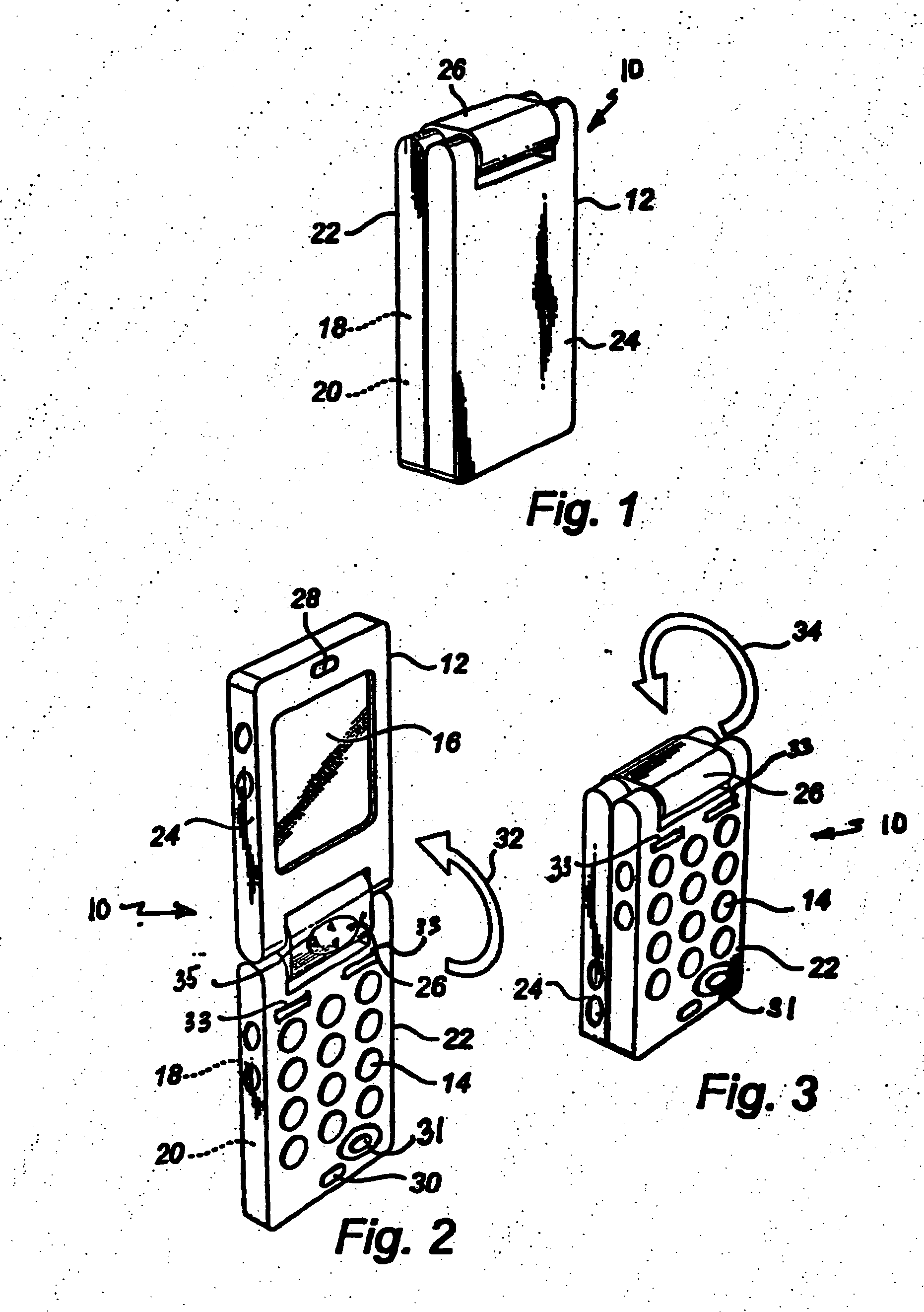
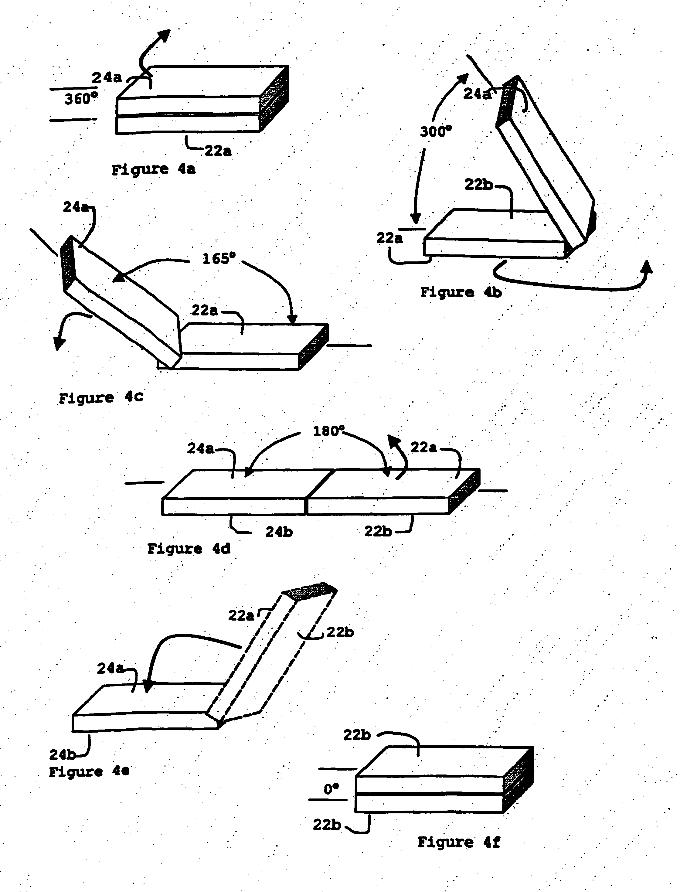
[0073] In the embodiment of this application, as shown in FIGS. 17-19, a multifunction device 200 is constructed having panel 222 and 224 attached together by hinge 226 that provides 360° relative movement between the panels, as in the other embodiments described above. A camera is contained within panel 222 with a lens 231 providing a viewing range extending outward from the face 222a of panel 222. In addition, a display 252 is mounted in face 222a of panel 222 and is operable both as a touch sensitive display, configured to provide a notepad mode of operation (shown in FIG. 18) and an image display configured to present photos or video (shown in FIG. 17). The camera feature of the embodiment, shown in FIG. 17, is enabled in the 360° position of panels 222 and 224. A display 216 is mounted on face 224a of panel 224 and is operable as the view finder of the camera lens 231.

[0074] The camera is operated by means of a zoom-in key 253 and a zoom-out key 254 in c...


PUM


Abstract

A multi-function electronic device, consists of two panels attached for relative movement by a hinge that provides a range of movement of a full 360°. A camera function is provided that includes a display screen visible to the subject of a picture to be captured. Attracter images are displayed on the screen to attract the attention of the subject.

Description

CROSS-REFERENCE TO RELATED APPLICATIONS [0001] This application is a continuation-in-part application and claims priority from, U.S. application Ser. No. 11 / 024,402, filed Dec. 30, 2004 which is a continuation-in-part application of U.S. application Ser. No. 10 / 829,415 filed on Apr. 21, 2004, now pending. This application and U.S. patent application Ser. No. 10 / 829,415 claim priority to U.S. patent application Ser. No. 10 / 421,278, filed on Apr. 23, 2003, now pending.BACKGROUND OF THE INVENTION [0002] 1. Field of the Invention [0003] The subject matter of this application relates to an arrangement of components that combines the functions of a multi-use electronic device to optimize their usefulness. More specifically, this application describes a unique arrangement of a two panel electronic device, optimized for use with a digital camera feature. [0004] 2. Brief Description of Related Developments [0005] Mobile telephones and similar communication devices are rapidly expanding in us...

Claims


Application Information

Patent Timeline
IPC IPC(8): G03B15/03H04M1/00H04M1/02H04Q7/20
CPCE05D3/122H04N21/64322H04L47/621H04L49/90H04M1/0218H04M1/022H04M1/0243H04M2250/16H04M2250/22H04M2250/52H04N1/00496H04N1/00525H04N1/00535H04N5/23293H04N21/44004E05Y2900/606G06F1/1681H04N23/531
Inventor ANDERSSON, TAGEKIELDSEN, KATJAMATTHIASSEN, BENNYDAM, OLE LOFTLUNDHELIN, TOTTIJACOBSEN, NIELS EBBE
Owner NOKIA CORP
Why Eureka
Try Eureka