Image forming apparatus

a technology of forming apparatus and developing roller, which is applied in the direction of electrographic process apparatus, instruments, optics, etc., can solve the problems of compromising high resolution, difficult to achieve high speed rotation of developing roller, and difficult to achieve high speed rotation. , to achieve the effect of reducing vibration and nois

Inactive Publication Date: 2006-02-16
S PRINTING SOLUTION CO LTD
View PDF6 Cites 178 Cited by
  • Summary
  • Abstract
  • Description
  • Claims
  • Application Information

AI Technical Summary

Benefits of technology

[0012] An aspect of the present invention is to solve at least the above problems and / or disadvantages and to provide at least the advantages described below. Accordingly, an aspect of the present invention is to provide an improved image forming apparatus using a combination of contact and non-contact type developing methods to exactly receive driving power to minimize vibration and noise.

Problems solved by technology

However, high speed rotation of the developing roller is relatively difficult to achieve.
High speed rotation is relatively difficult because the developing roller wears due to contact with the photosensitive body.
Therefore, high resolution may be compromised, and the surface of the developing roller may be pressed when the developing roller is not used for a long period.
However, toner on the surface of the developing roller is often scattered due to the high speed rotation.
Thus, the developing roller may become contaminated and may not able to maintain the predetermined developing gap.
As a result, the developing roller has a relatively complicated structure.

Method used


Image

  • Image forming apparatus
  • Image forming apparatus
  • Image forming apparatus

Examples


Embodiment Construction

[0031] The matters defined in the description such as a detailed construction and elements are provided to assist in a comprehensive understanding of the embodiments of the invention. Accordingly, those of ordinary skill in the art will recognize that various changes and modifications of the embodiments described herein can be made without departing from the scope and spirit of the invention. Also, descriptions of well-known functions and constructions are omitted for clarity and conciseness.

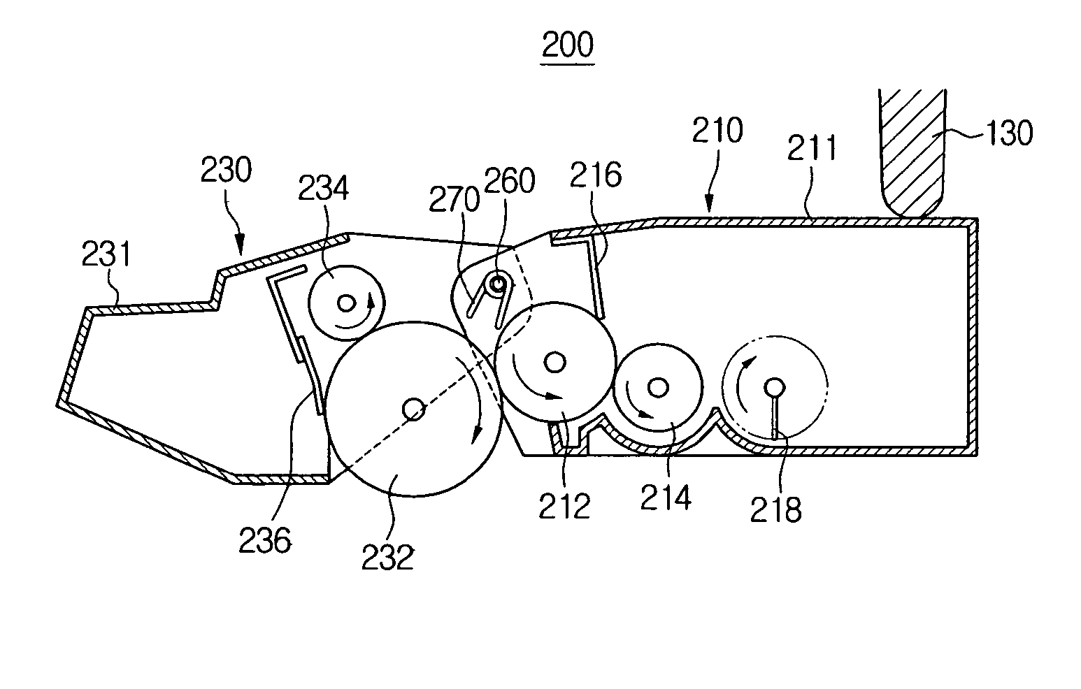
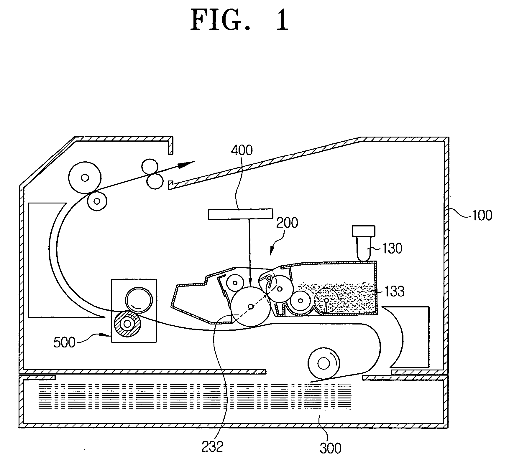
[0032]FIG. 1 is a schematic view of an image forming apparatus in accordance with an embodiment of the present invention. Referring to FIG. 1, the image forming apparatus comprises a developing unit 200 installed inside a body 100. The body 100 includes first and second developing units 230 and 210, a pressing member 130, a hinge shaft 260, a first elastic member 270, a paper feeding unit 300, a laser scanning unit 400, and a fixing unit 500.

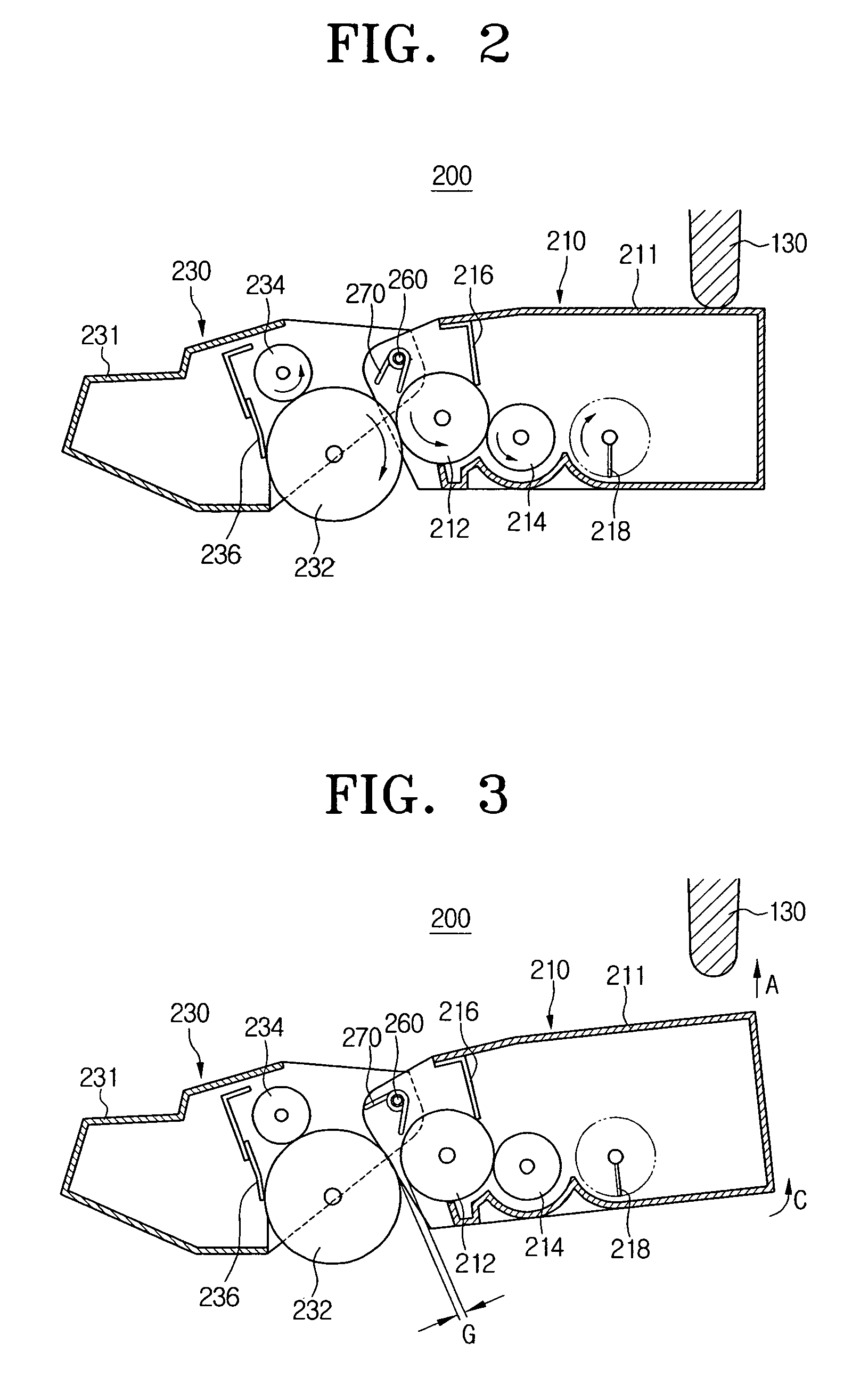
[0033] As shown in FIG. 2, the developing unit 200 c...


PUM


Abstract

An improved image forming apparatus comprises a first developing unit comprising a photosensitive body. Also provided is a second developing unit including a developing roller which is moveably installed so that the developing roller selectively contacts the photosensitive body. A pressing member selectively presses the second developing unit. The developing roller contacts the photosensitive body during a developing process and separates from the photosensitive body after the developing process is finished.

Description

CROSS-REFERENCE TO RELATED APPLICATIONS [0001] This application claims the benefit under 35 U.S.C. 119(a) of Korean Patent Application No. 2004-64003, filed Aug. 13, 2004, the entire disclosure of which is hereby incorporated by reference. BACKGROUND OF THE INVENTION [0002] 1. Field of the Invention [0003] The present invention relates to an image forming apparatus. More particularly, the present invention relates to an image forming apparatus in which a developing roller makes contact with a photosensitive body during an image developing process and separates from the photosensitive body after the developing process is finished. [0004] 2. Description of the Related Art [0005] In general, image forming apparatuses, such as laser printers, light emitting diode (LED) printers, digital copiers, facsimiles, and multi-functional devices, transfer an image signal. The image signal is transferred according to an input digital signal, as a visible image, to a printing medium such as a sheet...

Claims


Application Information

Patent Timeline
Patent Type & Authority Applications(United States)
IPC IPC(8): G03G15/01
CPCG03G2221/1861G03G21/1825G03G15/0808G03G15/0896G03G2221/1657
Inventor KIM, YOUNG-MINPARK, SANG-CHEOL
Owner S PRINTING SOLUTION CO LTD
Why Eureka
Try Eureka