Anterior prosthetic spinal disc replacement

a prosthetic and spinal disc technology, applied in the field of prosthetic spinal discs, can solve the problems of spinal disc displacement or damage, leg pain, loss of muscle control, and even paralysis, and achieve the effects of reducing the risk of spinal disc damage, and improving the quality of li

Active Publication Date: 2006-02-16
GLOBUS MEDICAL INC
View PDF83 Cites 243 Cited by
  • Summary
  • Abstract
  • Description
  • Claims
  • Application Information

AI Technical Summary

Benefits of technology

[0022] The artificial disc may also have mechanical stops that limit movement of the disc. For example, stops may be provided to prevent lateral bending greater than 10 degrees in each direction. In addition, mechanical stops may prevent total axial rotation greater than 5 to 10 degrees.

Problems solved by technology

The spinal disc may be displaced or damaged due to trauma, disease, degenerative defects, or wear over an extended period.
The mass of a herniated or “slipped” nucleus tissue can compress a spinal nerve, resulting in leg pain, loss of muscle control, or even paralysis.
As these overlapping laminated plies of the annulus begin to buckle and separate, either circumferential or radial annular tears may occur, which may contribute to persistent or disabling back pain.
Adjacent, ancillary spinal facet joints will also be forced into an overriding position, which may create additional back pain.
Whenever the nucleus tissue is herniated or removed by surgery, the disc space will narrow and may lose much of its normal stability.
While this treatment alleviates the pain, all discal motion is lost in the fused segment.
Ultimately, this procedure places a greater stress on the discs adjacent to the fused segment as they compensate for lack of motion, perhaps leading to premature degeneration of those adjacent discs.
These devices have met with less than ideal results and improved designs are needed.
While anterior implantation involves numerous risks during surgery, including potential damage to organs during surgery and increased risk to the various blood vessels during surgery, improved designs and methods of implantation may increase the desirability of anterior approaches to prosthetic disc replacements.
Despite this advantage, a posterior approach also raises other difficulties that have discouraged it use.
For instance, during a posterior approach the spinal cord is exposed and potentially at risk of damage.
Additionally, vertebral body geometry allows only limited access to the intervertebral discs.

Method used


Image

  • Anterior prosthetic spinal disc replacement
  • Anterior prosthetic spinal disc replacement
  • Anterior prosthetic spinal disc replacement

Examples


Embodiment Construction

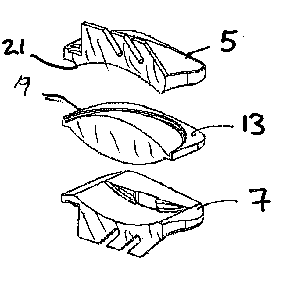
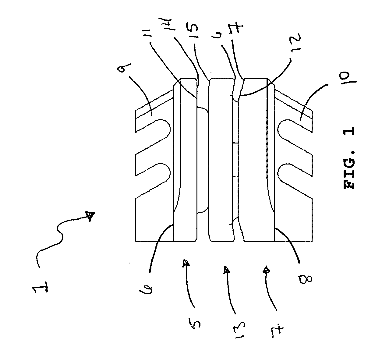
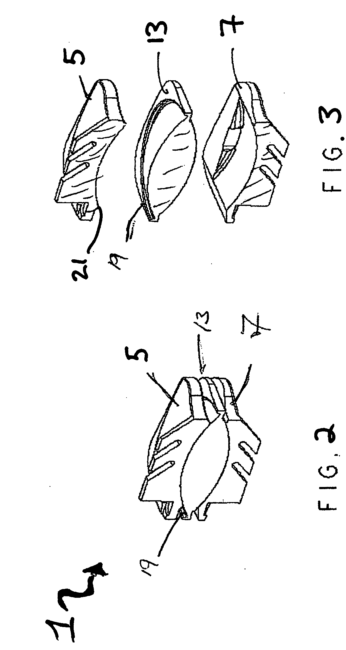
[0055] The present invention relates generally to a prosthetic spinal disc for replacing a damaged disc between two vertebrae of a spine. The present invention also relates to a method for implanting a prosthetic spinal disc via anterior implantation. In particular, the present invention encompasses a method for implanting the prosthetic spinal disc via an anterior approach.

[0056] As described in detail below, the prosthetic spinal disc may be articulating or non-articulating.

[0057] Several embodiments of the invention illustrate different examples of how the interfacing surfaces of an articulating prosthetic disc may be formed. For instance, articulation may be accomplished with one interfacing surface, such as a ball and joint, or alternatively may be accomplished with two or more interfacing surfaces such as a core disposed between an upper and lower articulating surface. The configuration of the surface contact may vary to permit or restrict different types and ranges of motio...


PUM

PropertyMeasurementUnit
heightaaaaaaaaaa
heightaaaaaaaaaa
angleaaaaaaaaaa

Abstract

The present invention relates generally to a prosthetic spinal disc for replacing a damaged disc between two vertebrae of a spine. The present invention also relates to a method for implanting a prosthetic spinal disc via anterior or anterior lateral implantation. Other surgical approaches for implanting the prosthetic disc may also be used.

Description

CROSS REFERENCE TO RELATED APPLICATIONS [0001] This application claims priority to U.S. application Ser. No. 10 / 909,210 filed on Jul. 30, 2004, U.S. application Ser. No. 10 / 827,642 filed on Apr. 20, 2004, and to provisional application Ser. No. 60 / 491,271 filed on Jul. 31, 2003, all of which are incorporated herein in their entireties by reference thereto.FIELD OF THE INVENTION [0002] The present invention relates to a prosthetic spinal disc for fully or partially replacing a damaged disc between two vertebrae of a spine. The present invention also relates to a method for implanting a prosthetic spinal disc via anterior, anterolateral, and lateral implantation, although other implantation approaches may also be used. BACKGROUND OF THE INVENTION [0003] The vertebral spine is the axis of the skeleton on which a substantial portion of the weight of the body is supported. In humans, the normal spine has seven cervical, twelve thoracic and five lumbar segments. The lumbar spine sits upon...

Claims


Application Information

Patent Timeline
Patent Type & Authority Applications(United States)
IPC IPC(8): A61F2/44A61B17/00A61B17/02A61B17/16A61B17/17A61B17/90A61FA61F2/00A61F2/02A61F2/30
CPCA61B17/1604A61F2310/00796A61B17/1735A61B17/1757A61B2017/0046A61B2017/0256A61F2/442A61F2/4425A61F2002/30014A61F2002/30113A61F2002/30125A61F2002/30166A61F2002/302A61F2002/30224A61F2002/30365A61F2002/30471A61F2002/30545A61F2002/30563A61F2002/30568A61F2002/30571A61F2002/30579A61F2002/30594A61F2002/30604A61F2002/30649A61F2002/30662A61F2002/30769A61F2002/30772A61F2002/30878A61F2002/30884A61F2002/443A61F2002/448A61F2220/0033A61F2220/0091A61F2230/0006A61F2230/0008A61F2230/0028A61F2230/0065A61F2230/0069A61F2250/001A61F2250/0018A61F2310/00407A61B17/1671A61F2230/0071
Inventor PAUL, DAVID C.ANGELUCCI, CHRISTOPHERRHODA, WILLIAMBOYER, MICHAEL L. IIDUFFIELD, WILLIAM E.
Owner GLOBUS MEDICAL INC
Why Eureka
Try Eureka