Juice extractor with juice manifold having side outlet for juice

Active Publication Date: 2006-02-23
JOHN BEAN TECH CORP
View PDF47 Cites 5 Cited by
  • Summary
  • Abstract
  • Description
  • Claims
  • Application Information

AI Technical Summary

Benefits of technology

[0004] The juice extractor of the present invention has an extractor frame and an interior defining a product material area. At least one pair of extractor cups are relatively moveable within the product material area. A strainer tube is mounted to receive juice and pulp and discharge juice therefrom. An orifice tube is moveable within the strainer tube fo

Problems solved by technology

This material is difficult to clean and can

Method used


Image

  • Juice extractor with juice manifold having side outlet for juice
  • Juice extractor with juice manifold having side outlet for juice
  • Juice extractor with juice manifold having side outlet for juice

Examples


Embodiment Construction

[0057] The present invention will now be described more fully hereinafter with reference to the accompanying drawings, in which preferred embodiments of the invention are shown. This invention may, however, be embodied in many different forms and should not be construed as limited to the embodiments set forth herein. Rather, these embodiments are provided so that this disclosure will be thorough and complete, and will fully convey the scope of the invention to those skilled in the art. Like numbers refer to like elements throughout, and prime notation is used to indicate similar elements in alternative embodiments.

[0058] The present invention provides many advantages over prior art juice extractors, such as disclosed in commonly assigned U.S. Pat. Nos. 2,649,730; 2,780,988; 3,717,084; 3,736,865; 4,300,449; 4,309,943; 4,309,944; 4,376,409; 4,700,620; 4,905,586; 4,922,813; 5,339,729; 5,483,870; 5,970,861; 5,992,311; 5,996,485; and 6,568,319, the disclosures which are hereby incorpora...


PUM


Abstract

A juice extractor includes extractor cups relatively moveable within a product material area that compress fruit therebetween. A strainer tube is mounted to receive juice and pulp and discharge juice therefrom. A juice manifold is positioned to collect the juice discharged from the strainer tube when an orifice tube moves therein. The juice manifold has an outlet positioned at a side of the extractor frame removed from the product material area to prevent build-up of peel and related byproducts.

Description

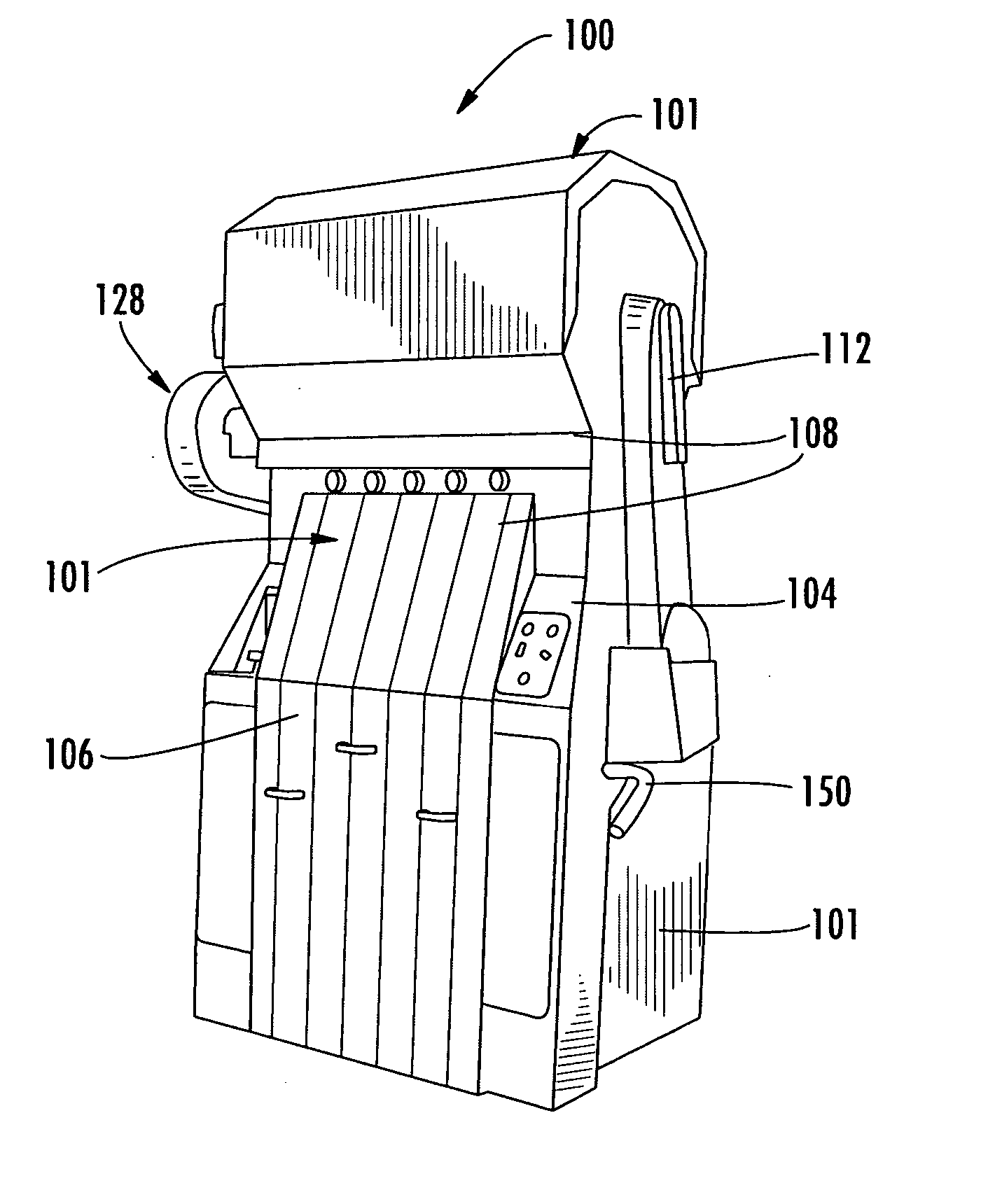
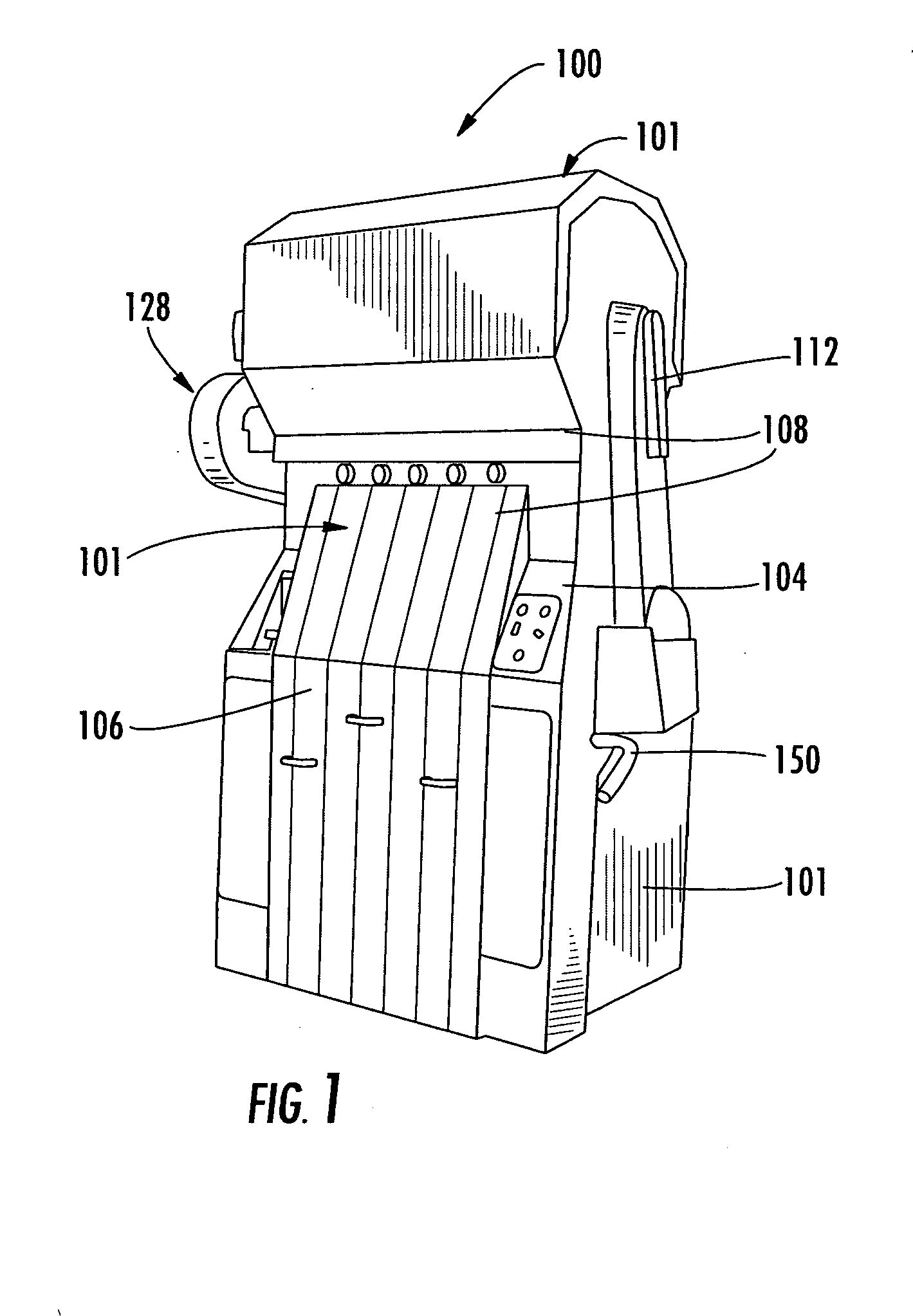
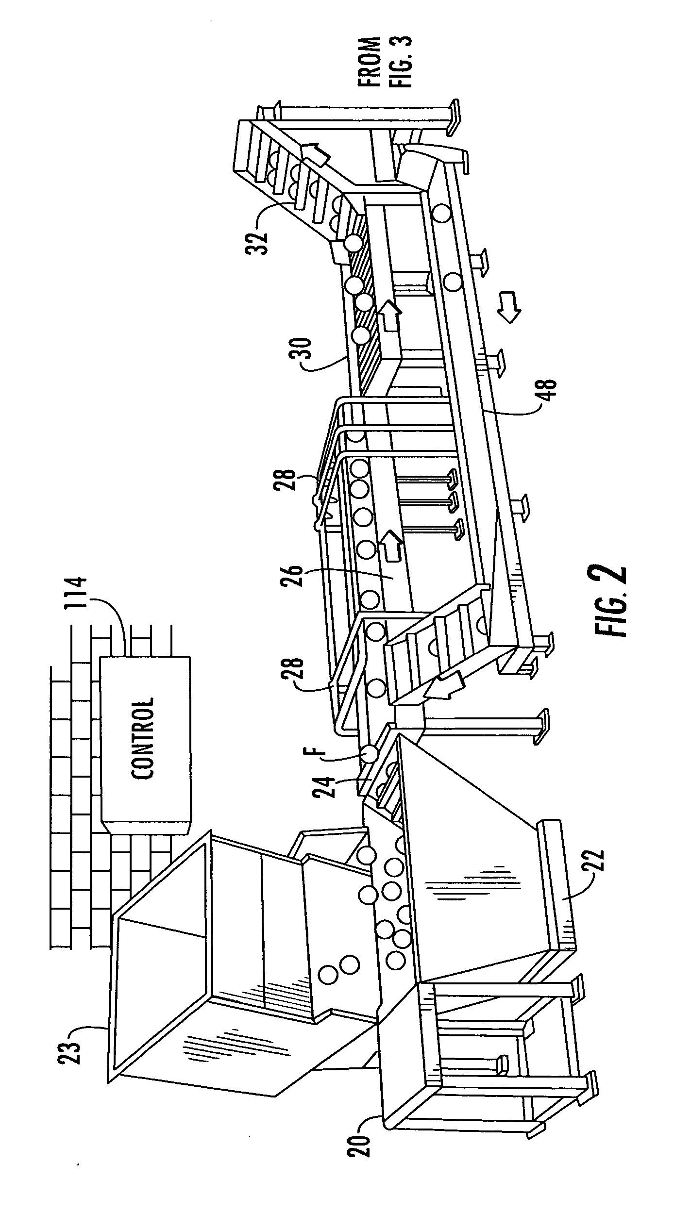
FIELD OF THE INVENTION [0001] The present invention relates to the field of juice extractors, and more particularly, this invention relates to juice extractors with a juice manifold for collecting juice. BACKGROUND OF THE INVENTION [0002] In a whole fruit juice extractor such as disclosed in commonly assigned U.S. Pat. Nos. 5,970,861; 5,992,311; 5,996,485; and 6,568,319, the disclosures which are hereby incorporated by reference in their entirety, a juice manifold is positioned to collect the juice discharged from a strainer tube, which receives an orifice tube moveable therein for generating pressure within the strainer tube to aid in discharging juice. In this type of juice extractor, the motion of extractor cups and the orifice tube received within the strainer tube are each controlled by a drive system, for example, drive cams supported by a camshaft at the top portion of the juice extractor. Although the motions are separate, they are synchronized, and as the juice is squeezed ...

Claims


Application Information

Patent Timeline
IPC IPC(8): B30B9/02
CPCA23N1/003
Inventor SCHRADER, GREGORY W.
Owner JOHN BEAN TECH CORP
Why Eureka
Try Eureka