Method of encoder signal compensation and apparatus thereof

a technology of encoder signal and compensation method, which is applied in the direction of printing, other printing apparatus, etc., can solve the problems of reducing printing quality, affecting so as to improve the output waveform of encoder signal and eliminate width errors

Inactive Publication Date: 2006-02-23
AETAS SYST
View PDF2 Cites 7 Cited by
  • Summary
  • Abstract
  • Description
  • Claims
  • Application Information

AI Technical Summary

Benefits of technology

[0012] An objective of the invention is to provide an encoder signal compensation method, which does not only effectively eliminate the width errors of the multiple encoder output signals, but also remove the phase errors at the same time.
[0013] Another objective of the invention is to provide an encoder signal compensation method, which effectively improves the output waveform of the encoder signal of printing and copying apparatuses, thereby increasing their printing quality.

Problems solved by technology

As seen in the above description, conventional printing apparatuses and copying apparatuses have encoder signal errors due to the mechanical precision errors, installation error of the encoder and even errors of the whole equipment.
It always results in a lower printing quality.

Method used


Image

  • Method of encoder signal compensation and apparatus thereof
  • Method of encoder signal compensation and apparatus thereof
  • Method of encoder signal compensation and apparatus thereof

Examples


Embodiment Construction

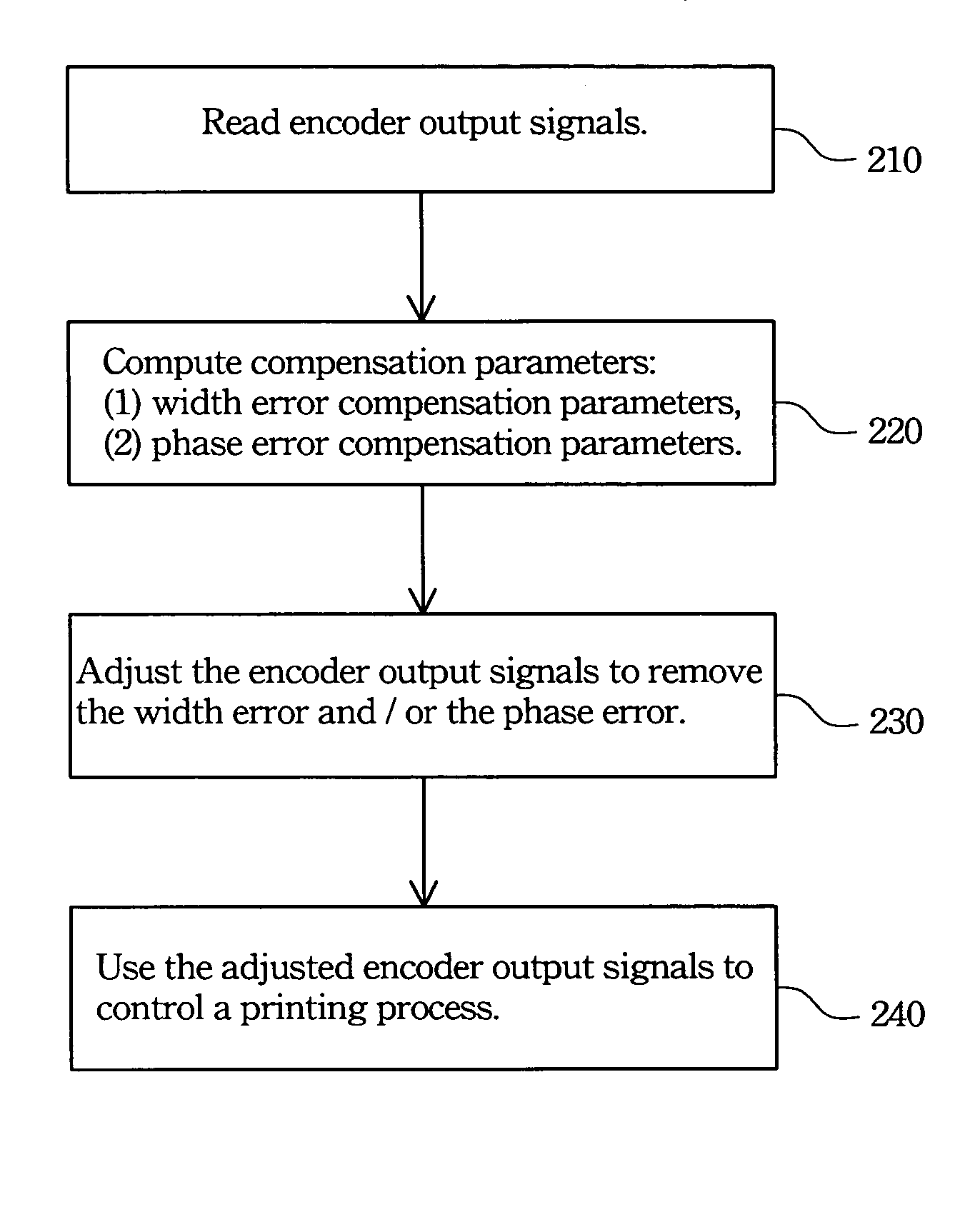
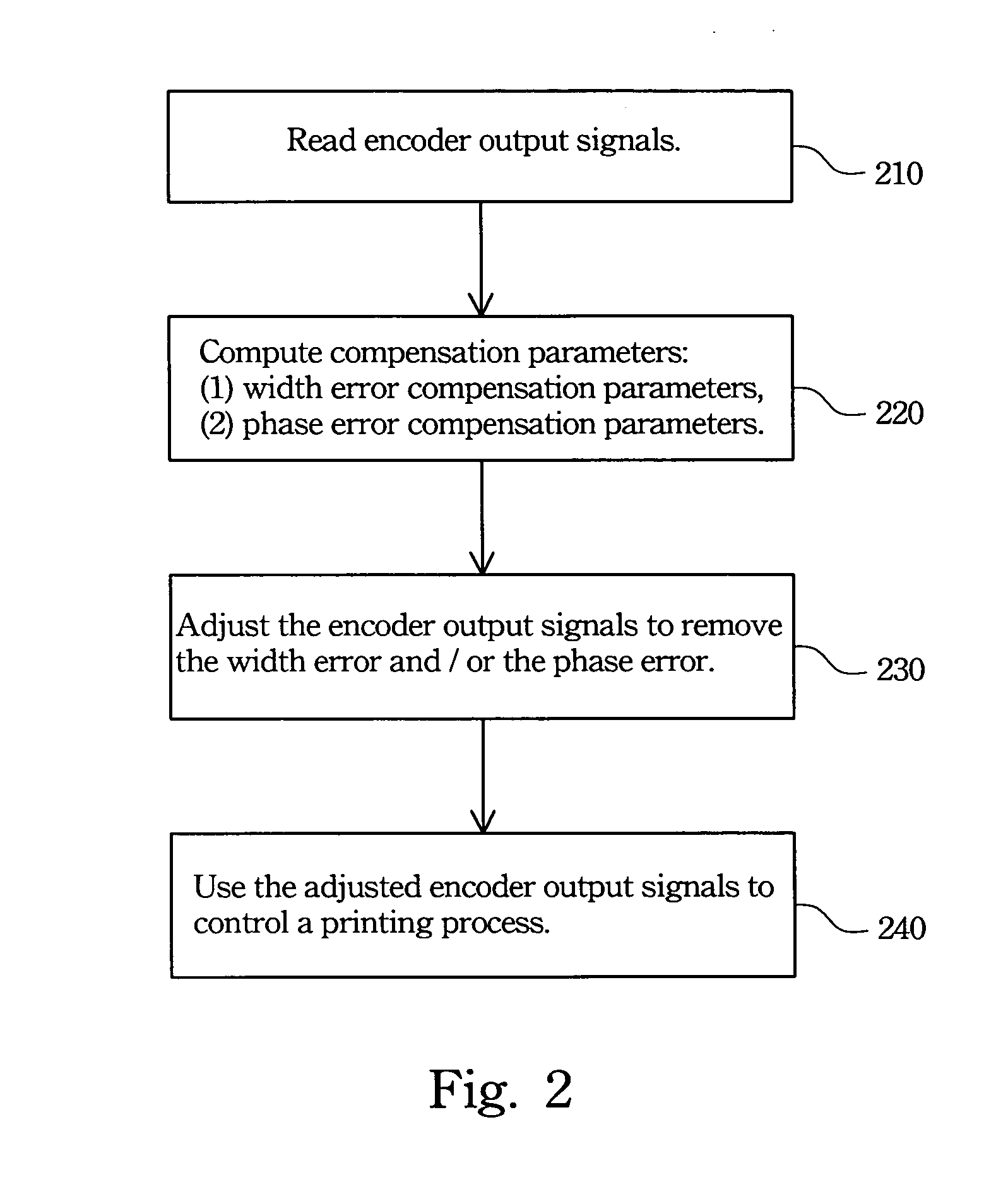
[0024] The disclosed encoder signal compensation method can effectively remove the phase and width error in the encoder signals, thereby increasing the printing quality of copying and printing apparatuses.

[0025] The procedure of the disclosed encoder signal compensation method is illustrated in FIG. 2. As shown in the chart, encoder output signals are read in step 210. As the encoder is installed after a printing apparatus, its precision error and installation error are generally fixed. After many times of tests, the output signal properties are fixed once the encoder is installed on the printing apparatus.

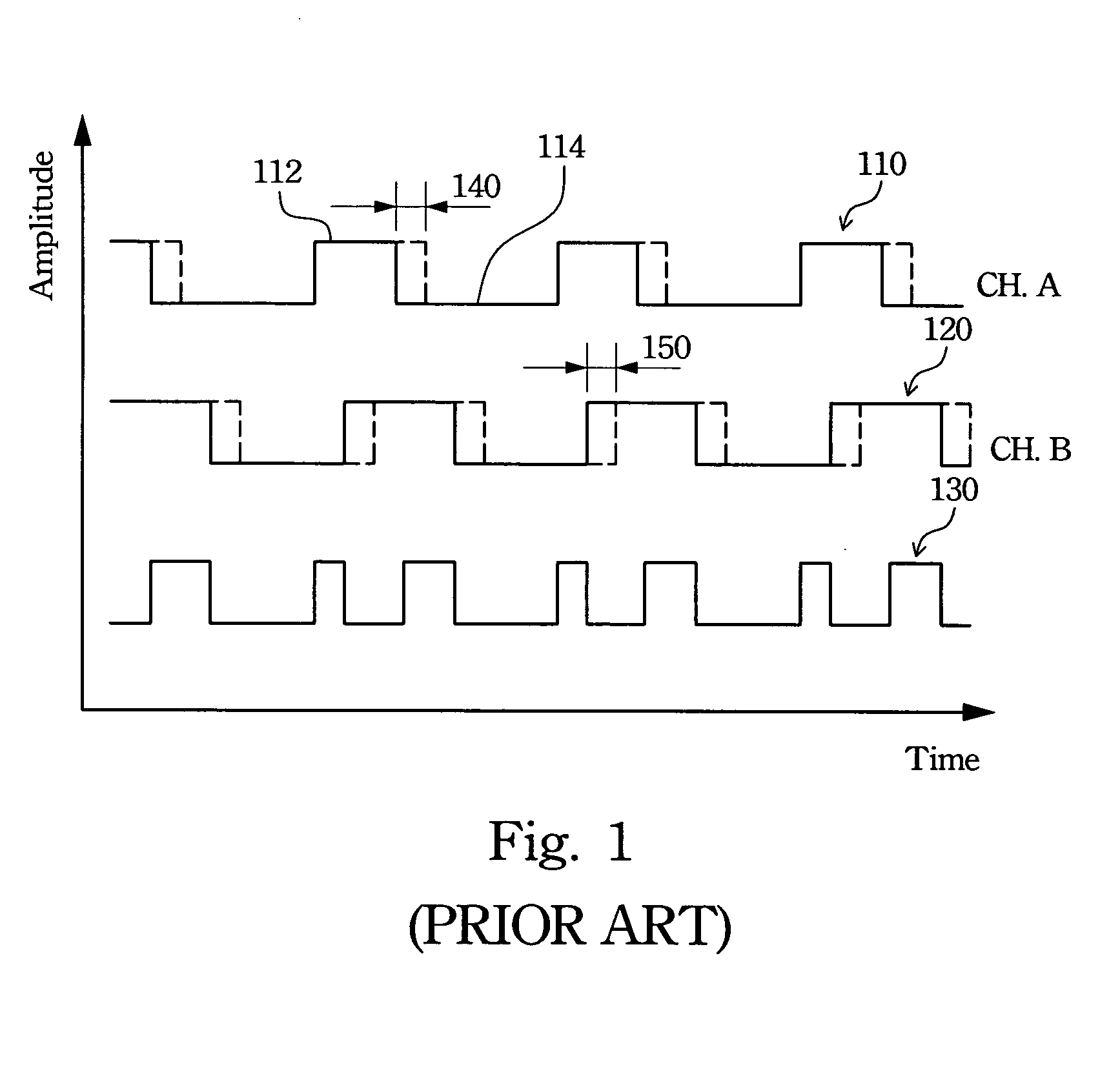
[0026] Compensation parameters including a width error compensation error and a phase error compensation parameter are computed in step 220. FIG. 3 explains how to compute the width error compensation parameter using the encoder output signal. When the printing apparatus prints under a normal printing status, the output signals of CH. A and / or CH. B of the encoder have the forms...


PUM


Abstract

An encoder signal compensation method and the apparatus thereof are described. The encoder signal compensation method includes the following steps. First, encoder output signals are read to calculate compensation parameters. Subsequent encoder output signals are compensated according to the calculated compensation parameters and the compensated encoder output signals are utilized to control a printing process. The encoder signal compensation method is effective in eliminating width errors and phase errors of the encoder output signals. Another embodiment of the invention is to provide a printing apparatus utilizing the encoder signal compensation method to reduce high frequency banding, effectively improving the printing quality.

Description

BACKGROUND OF THE INVENTION [0001] 1. Related Applications [0002] The present application is based on, and claims priority from, Taiwan Application Ser. No. 93125029, filed Aug. 19, 2004, the disclosure of which is hereby incorporated by reference herein in its entirety. [0003] 2. Field of Invention [0004] The invention pertains to an encoder signal compensation method and the apparatus thereof. In particular, it relates to a compensation method for the encoder signals of printing apparatuses and the printing apparatus thereof. [0005] 3. Related Art [0006] With the rapid development in the electronic industry, printing apparatuses such as copiers and printers have been widely used in daily life. Besides large companies, copiers and laser printers are already popular in various kinds of places, including families. The operations of copiers and laser printers rely on opto-electronic image printing techniques. Advanced opto-electronic image printing techniques enables manufacturers to ...

Claims


Application Information

Patent Timeline
Patent Type & Authority Applications(United States)
IPC IPC(8): B41J29/38
CPCB41J29/00B41J2/125
Inventor CHEN, CHUN-CHIANG
Owner AETAS SYST
Why Eureka
Try Eureka