System and method for projecting images onto a moving screen

a technology of moving screen and projection system, applied in the direction of printers, instruments, camera focus arrangement, etc., can solve the problems of limited area within which a viewing audience can be accommodated, the best viewing of pictures, and the inability to view conventional projection systems such as those used in movie theaters. to minimize or eliminate glare and spill-light, the effect of increasing awareness of specific exhibits

Active Publication Date: 2006-02-23
THINC DESIGN
View PDF4 Cites 70 Cited by
  • Summary
  • Abstract
  • Description
  • Claims
  • Application Information

AI Technical Summary

Benefits of technology

[0008] In accordance with one aspect of the invention, an imaging and display system for the display of visual-media content over a wide-angle field extending up to a full 360° azimuth is provided. The system provides presentations of still or moving images on a screen-display which is formed or shaped, supported and configured for rotation on at least one rotational axis of the system, and to optionally do so with synchronous and / or panning audio. The system also provides for support means for supporting the shape of any of a variety of screen-displays and to provide circumnavigable viewing of the display, or a multitude of vantage points exterior to the perimeter of the display, from which to view the visual content.
[0009] The present invention solves the above-described problems associated with projecting an image on a shaped, revolving screen by electronically synchronizing the motion of the screen to the projected image while providing for a black “moving matte” to be synchronously incorporated into the original image, thus compensating for the motion of the screen and its resultant shift in shape relative to the source of image projection to minimize or eliminate glare and spill-light. The black “moving matte” effectively blocks all of the image area that is at any given moment extraneous to the rotating screen.
[0010] In like manner, the screen can be translated or moved other than by rotation with a dynamic moving matte synchronously compensating for screen movement to minimize or eliminate glare and spill-light. A camera connected at the projection axis of each projector is configured to record a distorted image and send it to a signal processor capable of determining a projective transformation matrix. Using the projective transformation matrix, the signal processor determines the parameters for the matte. The matte is then sent to the respective projector and projected onto the screen along with image data. The black matte effectively blocks all of the image area that is at any given moment extraneous to the rotating screen. According to an alternative arrangement, the construction of the matte may be performed manually using various digital editing tools available in the art. The system also provides for keystone correction in a projector arbitrarily oriented with respect to the screen.
[0011] The screen can be configured having sufficient dimensions to facilitate either close proximity viewing, such as in theaters, hotel lobbies, amusement parks and the like, or viewing at a distance, and in the latter case, can readily be employed in arenas, stadiums and other large audience venues adapted to house and operate projection systems and arrangements. The display system can readily be employed as a multimedia learning center for use in educational and / or research facilities, such as in museums to increase awareness of specific exhibits on display or to educate an audience by surrounding them with a compilation of images and sound.

Problems solved by technology

One drawback associated with conventional projection systems that project onto a flat screen is that the picture is best viewed when the viewer's line of sight is precisely normal to the plane of the picture.
In such systems, special consideration must be given to the positioning of the display within its environment because, typically, conventional projection systems, such as those used in movie theaters, cannot be viewed from the rear or extreme sides.
Thus, the area within which a viewing audience can be accommodated is limited to locations with suitable sight lines.
This ideal condition is difficult to realize when several people wish to view the picture simultaneously from varied locations.
Projecting an image on a shaped, revolving screen presents several problems that will be apparent to those of skill in the art.
First, glare from the projection source is apparent to a viewer standing on the opposite side of the rotating screen around one or more of its edges as it moves.
Second, the resultant spill-light of portions of the image that miss the screen as it rotates fall upon the background surface of the theatre, its ceiling or floor surfaces, creating distracting patterns of light.
Additionally, when the projection axis of the system is not perpendicular to the viewing screen, a portion of the projected image may appear distorted (e.g., stretched or compressed).
Depending upon the resolution or detail of the image being projected, the distortion may significantly degrade one's appreciation of the image.

Method used


Image

  • System and method for projecting images onto a moving screen
  • System and method for projecting images onto a moving screen
  • System and method for projecting images onto a moving screen

Examples


Embodiment Construction

[0013] The following description is presented to enable any person skilled in the art to make and use the invention, and is provided in the context of particular applications of the invention and their requirements. Various modifications to the disclosed embodiments will be readily apparent to those skilled in the art and the general principles defined herein may be applied to other embodiments and applications without departing from the spirit and scope of the present invention. Thus, the present invention is not intended to be limited to the embodiments shown, but is to be accorded the widest scope consistent with the principles and features disclosed herein.

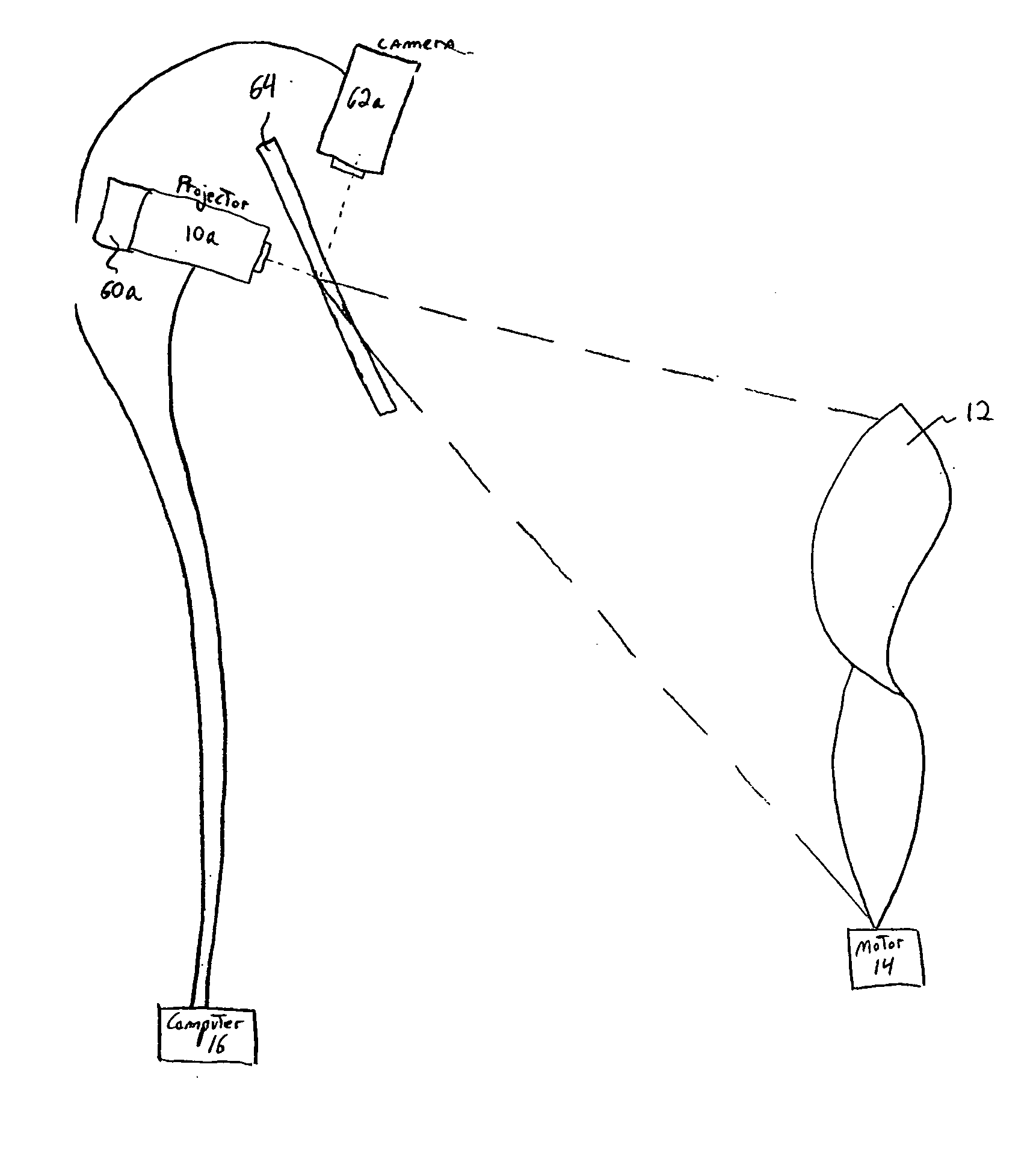
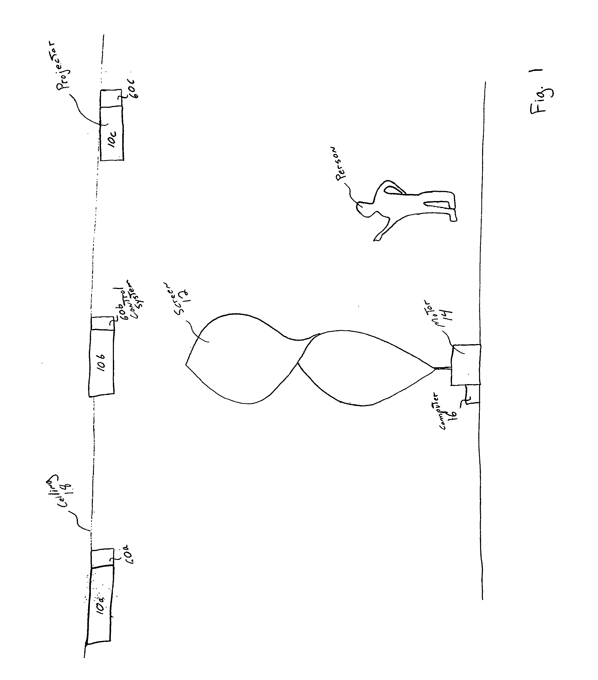
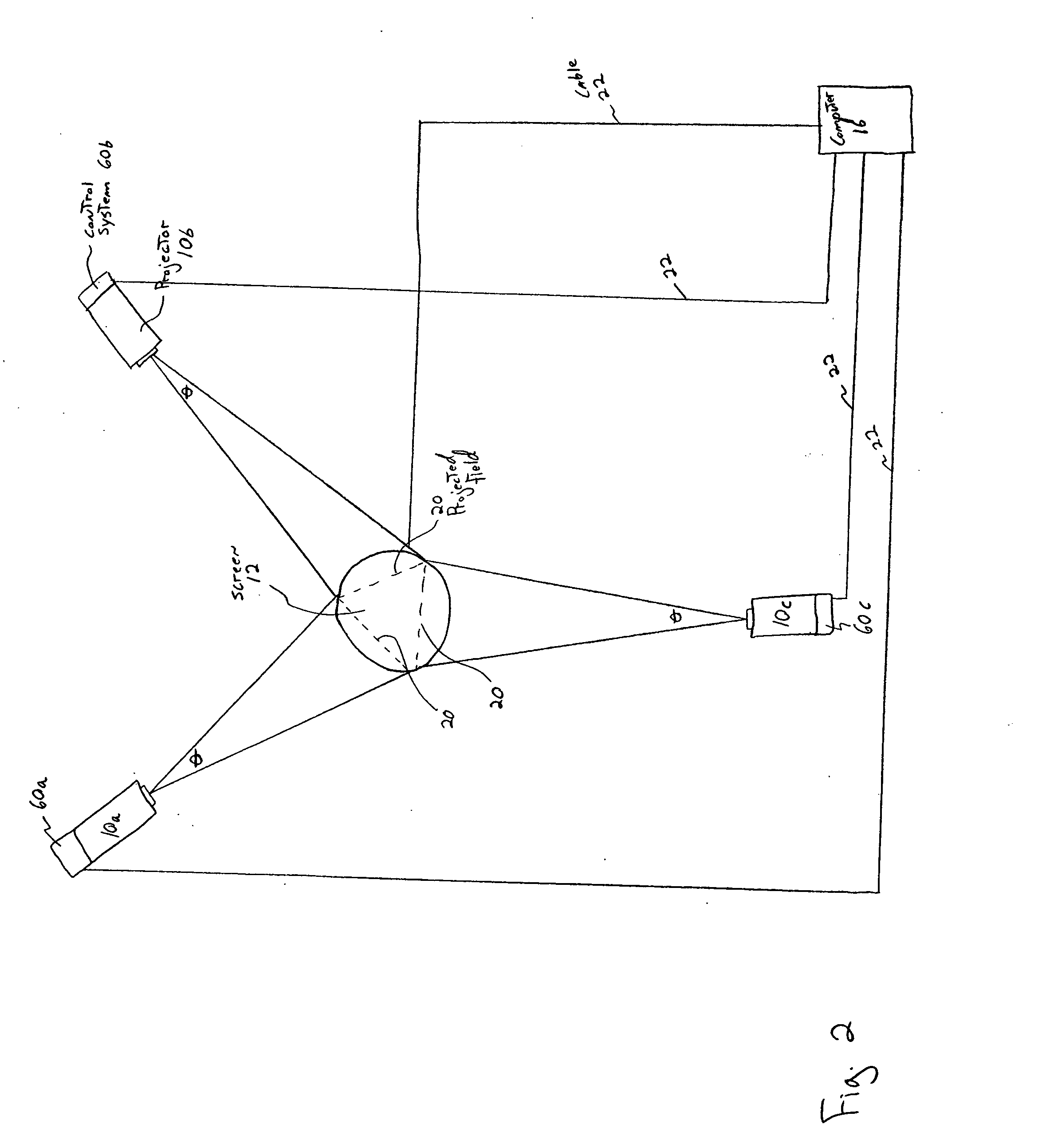
[0014] Various apparatuses and methods are described below for projecting an image onto a rotating shaped-screen utilizing at least two projectors operating simultaneously in a manner that allows optimal viewing equally well from a plurality of angles relative to the screen, up to 360° horizontally, eliminates glare from the ...


PUM


Abstract

A shaped screen rotates through one or more projected images of two or more projectors operating simultaneously, resulting in a dynamic, kinetic image surface which may be viewed equally well from a plurality of angles, up to 360° horizontally. By utilizing at least two projectors, the resultant composite image on the rotating screen is not only optimally viewed from any angle, but it is also animated by the movement of the screen itself, as well as by any animation within the projected image.

Description

[0001] Priority is claimed under 35 U.S.C. 119 to U.S. Provisional Application Ser. No. 60 / 590,000, filed on Jul. 21, 2004. The contents of this provisional application is hereby incorporated by reference in its entirety.FIELD OF THE INVENTION [0002] This invention relates to image projection, processing and displaying systems. More particularly, this invention relates to a method and apparatus for projecting live and / or pre-recorded visual content such as analog or digital video, film, slides and the like onto a centrally-located and movable screen to be viewed substantially simultaneously by an audience through potentially a 360° span without glare, spill-light or keystone distortion effecting the projected image. BACKGROUND OF THE INVENTION [0003] Most image projection systems consist of a projector and a flat screen. The projector produces an image through still slides, moving film or video. The flat screen receives the projected light and provides viewers with a planar image th...

Claims


Application Information

Patent Timeline
Patent Type & Authority Applications(United States)
IPC IPC(8): G03B21/26
CPCG03B21/26
Inventor HENNES, TOM
Owner THINC DESIGN
Why Eureka
Try Eureka