Methods, devices and computer program products for controlling power supplied to devices coupled to an uninterruptible power supply (UPS)

a technology of power supply and power supply device, applied in the direction of power supply for data processing, instruments, computing, etc., can solve the problems of only removing power from devices, affecting the operation of devices in standby mode, and affecting the operation of devices

Inactive Publication Date: 2006-02-23
POWERWARE
View PDF6 Cites 99 Cited by
  • Summary
  • Abstract
  • Description
  • Claims
  • Application Information

AI Technical Summary

Benefits of technology

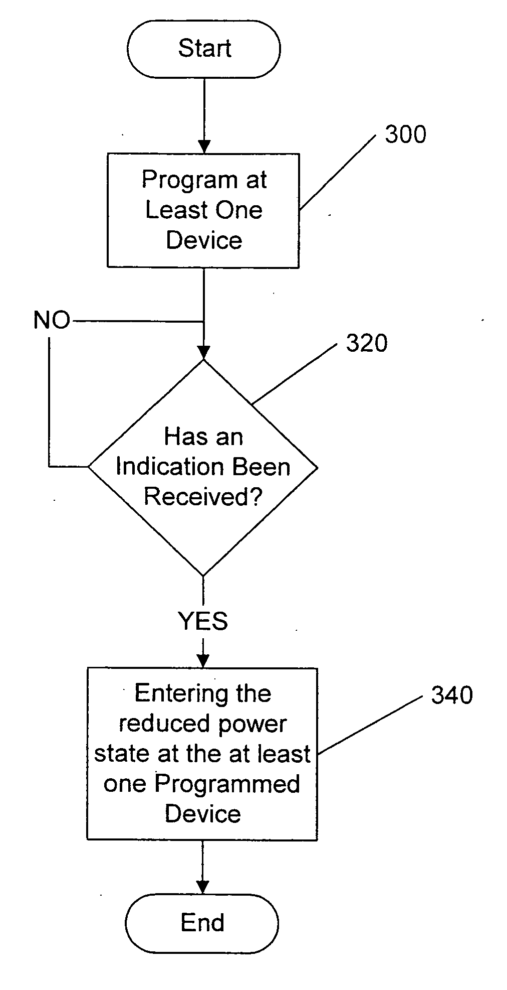
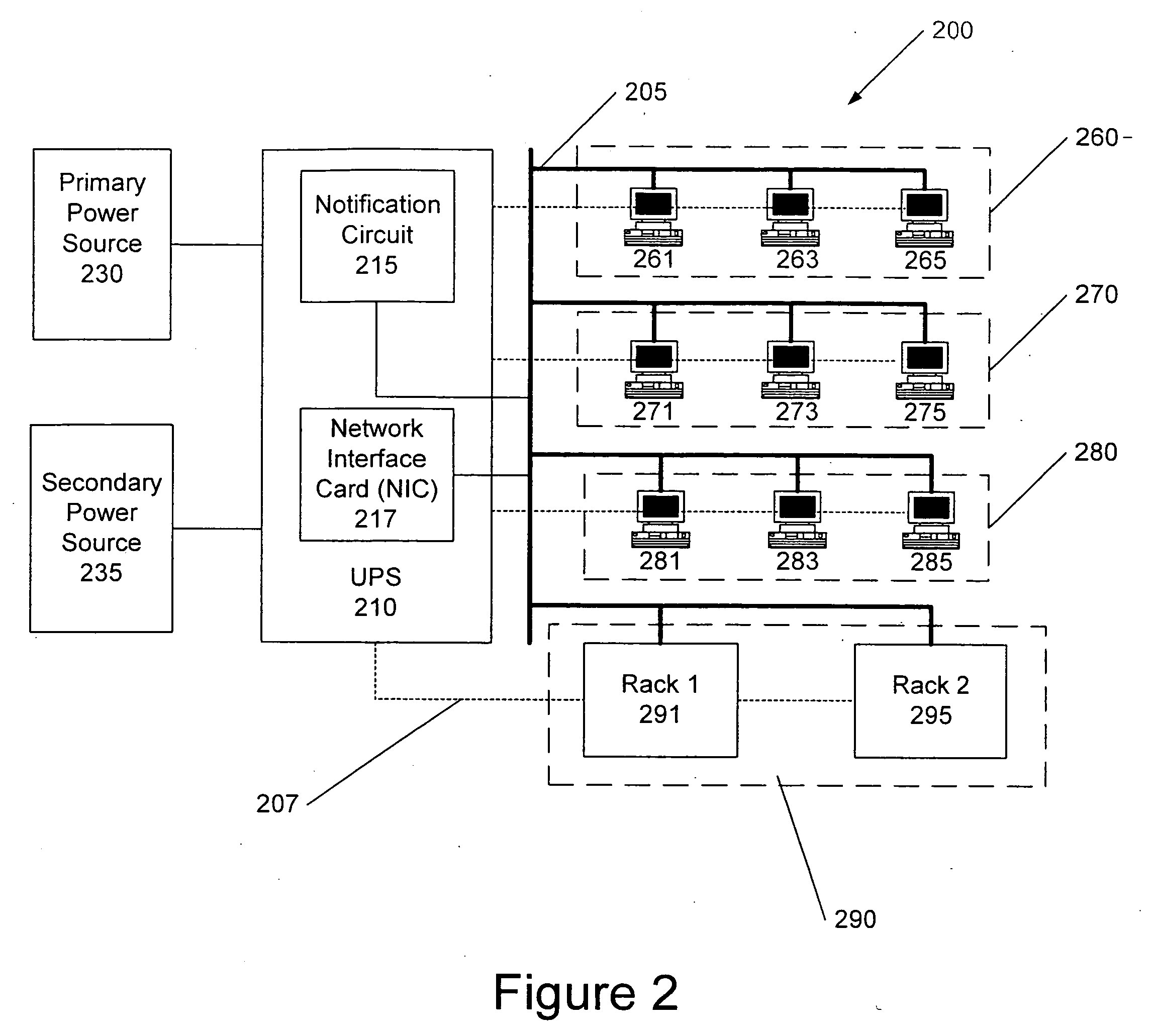
[0006] Some embodiments of the present invention provide methods, devices and computer program products for operating a networked device coupled to an uninterruptible power supply (UPS). One or more networked devices are programmed with priority information. The one or more networked devices are further programmed to enter a reduced power state based on the priority information following receipt of a power interruption indication signal from the UPS. The power interruption indication signal indicates that power from a primary source of power has been interrupted.

Problems solved by technology

Typically power can only be removed from devices being power by the UPS by turning off the UPS or by removing power from all of the devices plugged into a load segment.
Accordingly, this could become very cumbersome for a system administrator.
Thus, the devices in standby mode may still be drawing some power from the backup source.
Furthermore, once the primary power source is restored, each of the devices placed in standby mode may have to be awakened manually before service can be fully restored.
This can be quite time consuming if the UPS is used to provide power to an entire office building including hundreds of servers, all of which were put in standby mode during the power loss.

Method used


Image

  • Methods, devices and computer program products for controlling power supplied to devices coupled to an uninterruptible power supply (UPS)
  • Methods, devices and computer program products for controlling power supplied to devices coupled to an uninterruptible power supply (UPS)
  • Methods, devices and computer program products for controlling power supplied to devices coupled to an uninterruptible power supply (UPS)

Examples


Embodiment Construction

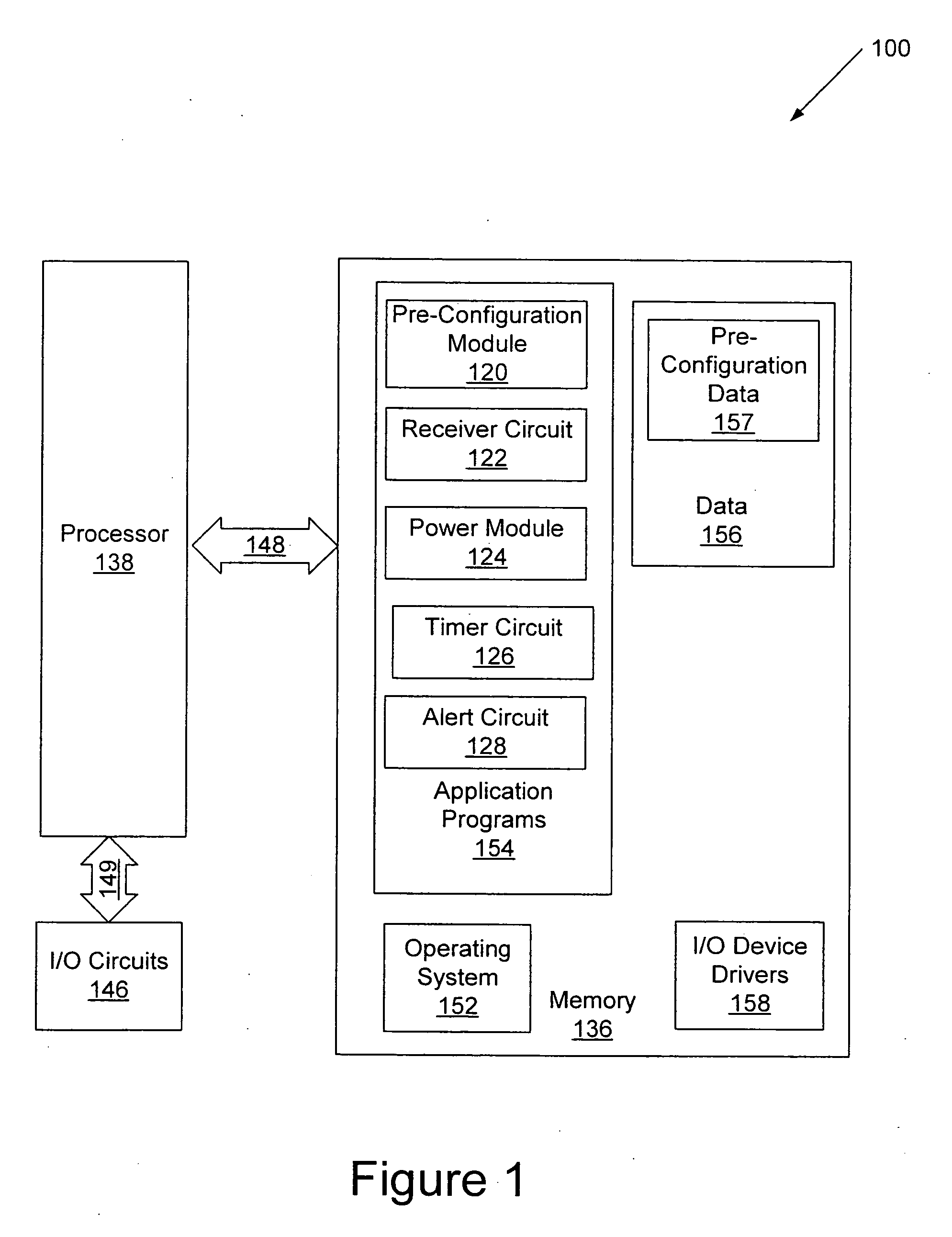
[0025] Specific exemplary embodiments of the invention now will be described with reference to the accompanying drawings. This invention may, however, be embodied in many different forms and should not be construed as limited to the embodiments set forth herein; rather, these embodiments are provided so that this disclosure will be thorough and complete, and will fully convey the scope of the invention to those skilled in the art. In the drawings, like numbers refer to like elements throughout. It will be understood that when an element is referred to as being “connected” or “coupled” to another element, it can be directly connected or coupled to the other element or intervening elements may be present. Furthermore, “connected” or “coupled” as used herein may include wirelessly connected or coupled. As used herein the term “and / or” includes any and all combinations of one or more of the associated listed items.

[0026] It will be understood that, although the terms first, second, etc...


PUM


Abstract

Methods, devices, systems and computer program products for operating a networked device coupled to an uninterruptible power supply (UPS) are provided. One or more networked devices are programmed with priority information. The one or more networked devices are further programmed to enter a reduced power state based on the priority information following receipt of a power interruption indication signal from the UPS. The power interruption indication signal indicates that power from a primary source of power has been interrupted.

Description

BACKGROUND OF THE INVENTION [0001] The present invention relates to power supply apparatus and methods of operation thereof, and more particularly, to uninterruptible power supplies (UPSs) and methods of operation thereof. [0002] UPSs are commonly used to provide conditioned and / or auxiliary power to electronic equipment that provides critical functions, such as computer systems, telecommunications systems and medical equipment. Typically, UPSs can provide AC power from a backup source, such as a battery, generator or fuel cell, in the event that a utility power supply fails or becomes degraded. [0003] A single UPS may be used to provide backup power to a large number of devices, for example, servers, monitors, coffee makers, refrigerators and the like. When the utility power is lost or becomes degraded, the UPS may provide power to all of these devices from the backup source. Conventional UPSs may include one or more load segments, i.e., groups of receptacles that can be independen...

Claims


Application Information

Patent Timeline
Patent Type & Authority Applications(United States)
IPC IPC(8): G06F1/30
CPCH04L12/10G06F1/3209
Inventor MAXWELL, MARCUS A.CUMMINS, DENNIS
Owner POWERWARE
Why Eureka
Try Eureka