

Front-wheel drive steering compensation method and system
a front-wheel drive and steering compensation technology, applied in the direction of tractor steering, soil-shifting machines/dredgers, transportation and packaging, etc., can solve the problems of reducing the steering increasing the turning radius, and limited turning ability of the motor grader
- Summary
- Abstract
- Description
- Claims
- Application Information
AI Technical Summary
Benefits of technology
Problems solved by technology
Method used
Image

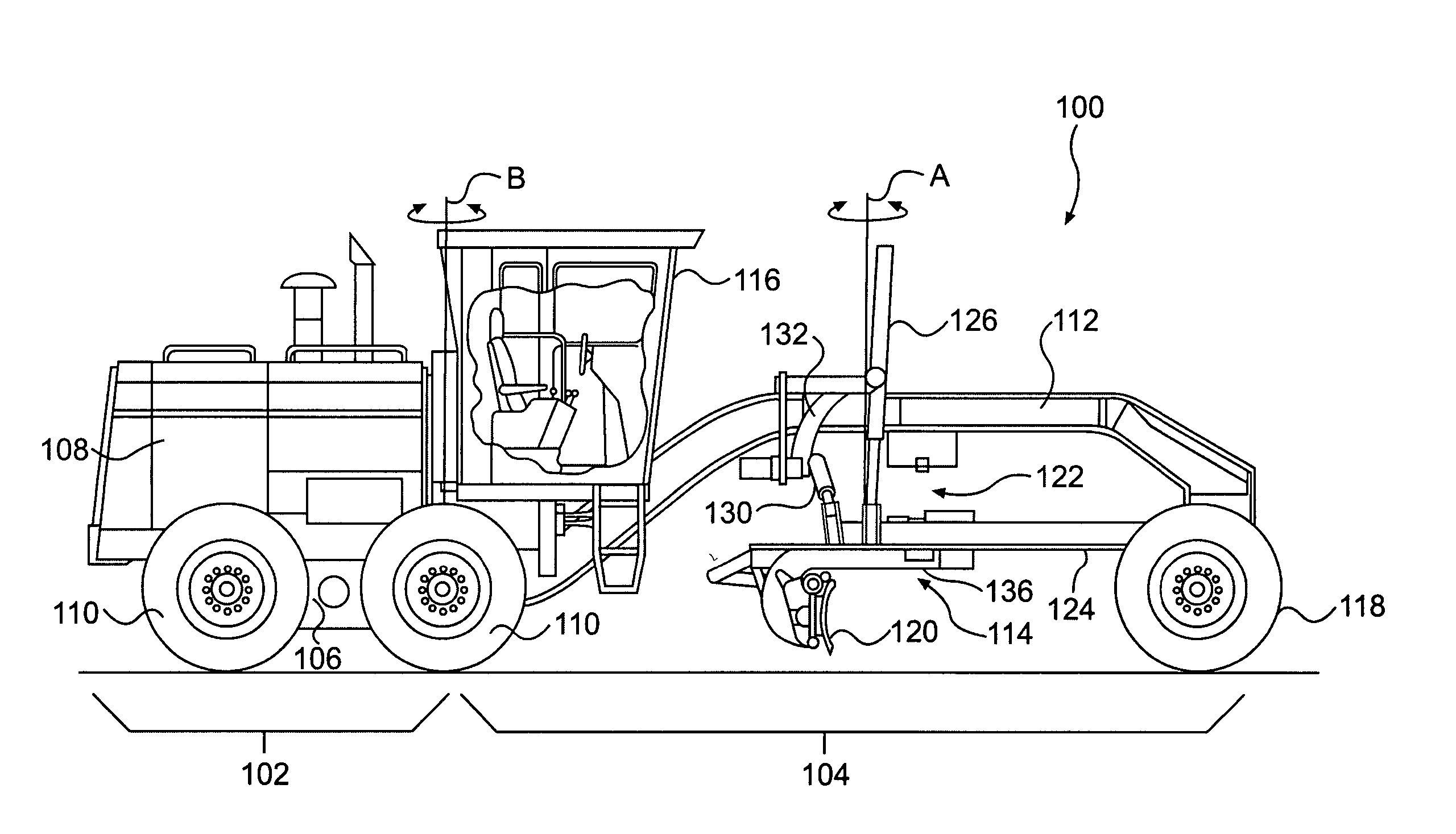
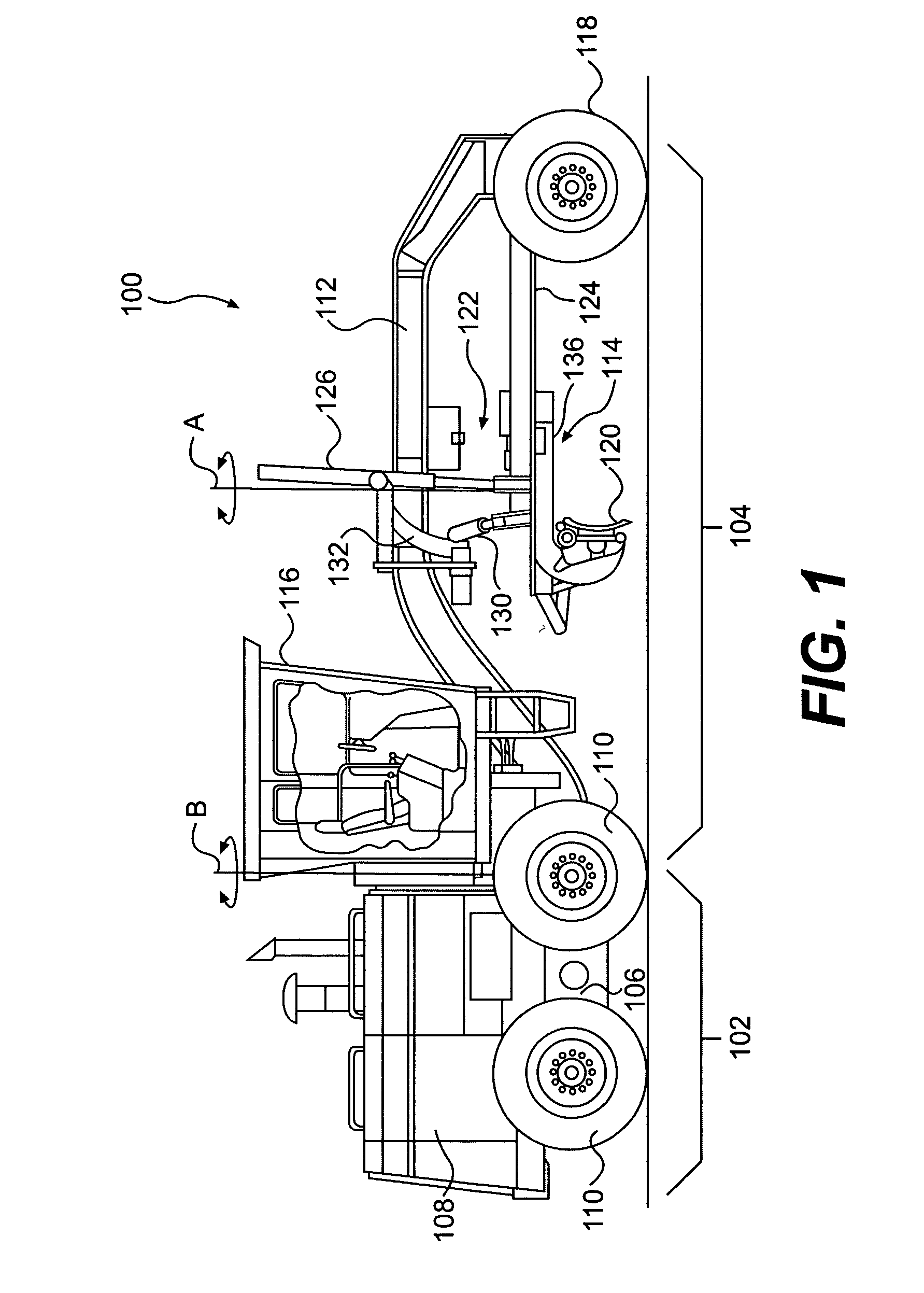
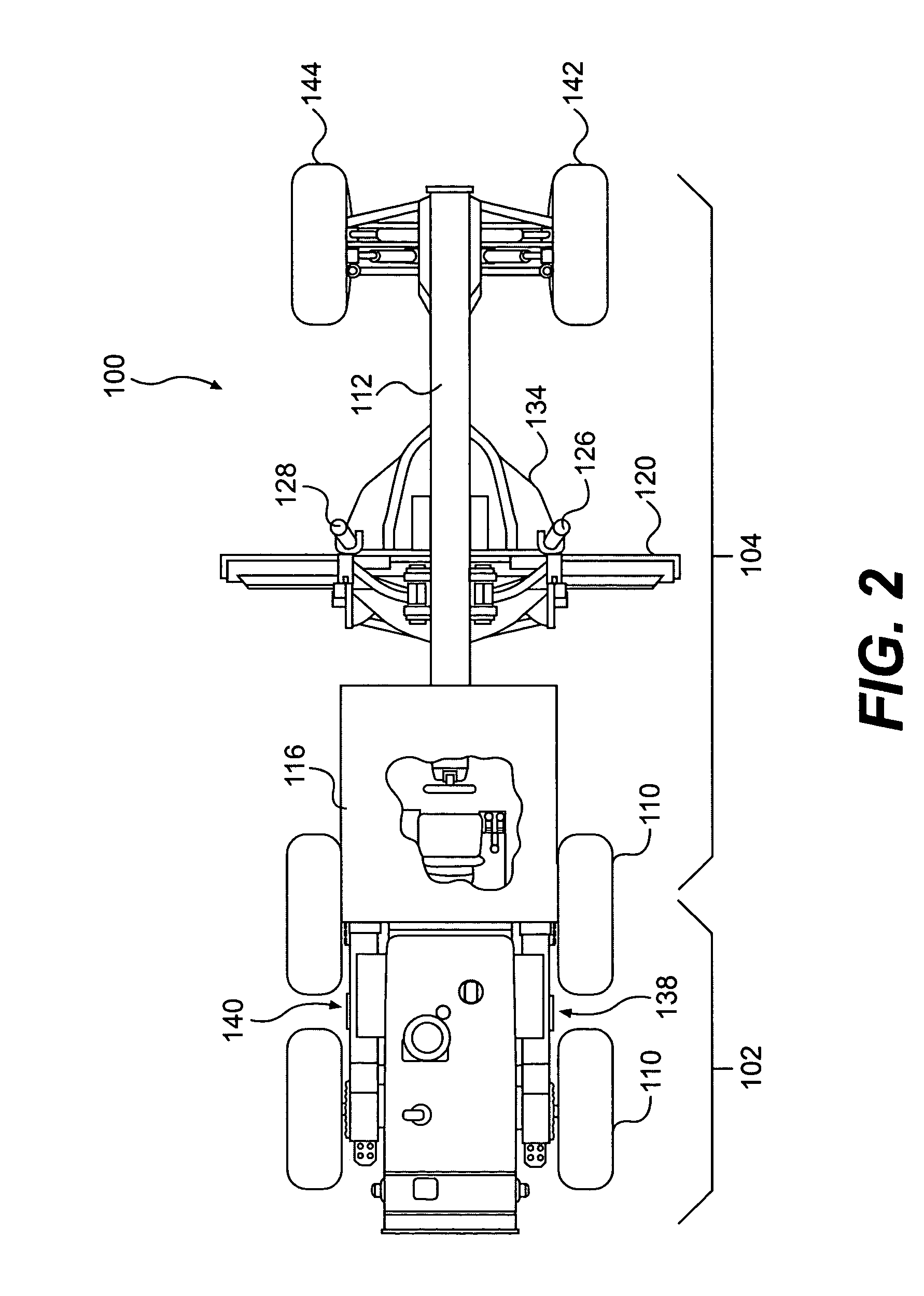
Examples
Embodiment Construction
[0011] Reference will now be made in detail to exemplary embodiments that are illustrated in the accompanying drawings. Wherever possible, the same reference numbers will be used throughout the drawings to refer to the same or like parts.
[0012] An exemplary embodiment of a motor grader 100 is illustrated in FIGS. 1 and 2. The motor grader 100 includes a rear frame section 102 and a front frame section 104. The rear frame section 102 includes a rear frame 106 and an engine in an engine compartment 108. The engine in the engine compartment 108 is mounted on the rear frame 106 and drives or powers rear wheels 110 on the motor grader 100.
[0013] The front frame section 104 includes a front frame 112, a blade assembly 114, and an operator cab 116. The front frame 112 extends from front wheels 118 toward the rear wheels 110, and supports the operator cab 116. The operator cab 116 contains the many controls necessary to operate the motor grader 100.
[0014] The blade assembly 114 includes ...
PUM
 Abstract
Description
Claims
Application Information