Wireless item location monitoring system and method

a monitoring system and wireless technology, applied in the field of wireless monitoring systems, can solve the problems of preventing thorough investigation based on suspicion alone, pets straying too far from home locations sometimes getting lost or stolen, and endangering themselves and becoming los

Inactive Publication Date: 2006-03-02
ELLIOTT ROBERT ODELL
View PDF18 Cites 35 Cited by
  • Summary
  • Abstract
  • Description
  • Claims
  • Application Information

AI Technical Summary

Benefits of technology

[0012] The foregoing and other objects of this invention are achieved by providing a wireless electronic tracking system employs transmitters attached to moveable target items that send continuous analog radio frequency (RF) digitally-coded signals at prime number differentiated time intervals to a base receiver. The coded signals carry transmitter and base unit identifiers, low battery and attachment status information. The base unit periodically scans using an omnidirectional antenna to determine distance and azimuth for multiple active transmitters, alerting an operator to any status alerts, such as ‘out of ra...

Problems solved by technology

Geriatric patients often move about freely within the boundaries of a resident hospital, but some could endanger themselves and become lost and unable to find their way home if they wander outside the grounds.
Likewise, pets straying too far from a home location sometimes get lost or stolen.
Expensive retail merchandise susceptible to shoplifting can be spirited away and if small enough hidden in the thief's pocket or packages, thereby deterring thorough investigation based on suspicion alone.
Horror stories abound of children or scuba divers on tours being left behind because an improper head count overlooked their absence.
Numerous prior art devices and sy...

Method used


Image

  • Wireless item location monitoring system and method
  • Wireless item location monitoring system and method
  • Wireless item location monitoring system and method

Examples


Embodiment Construction

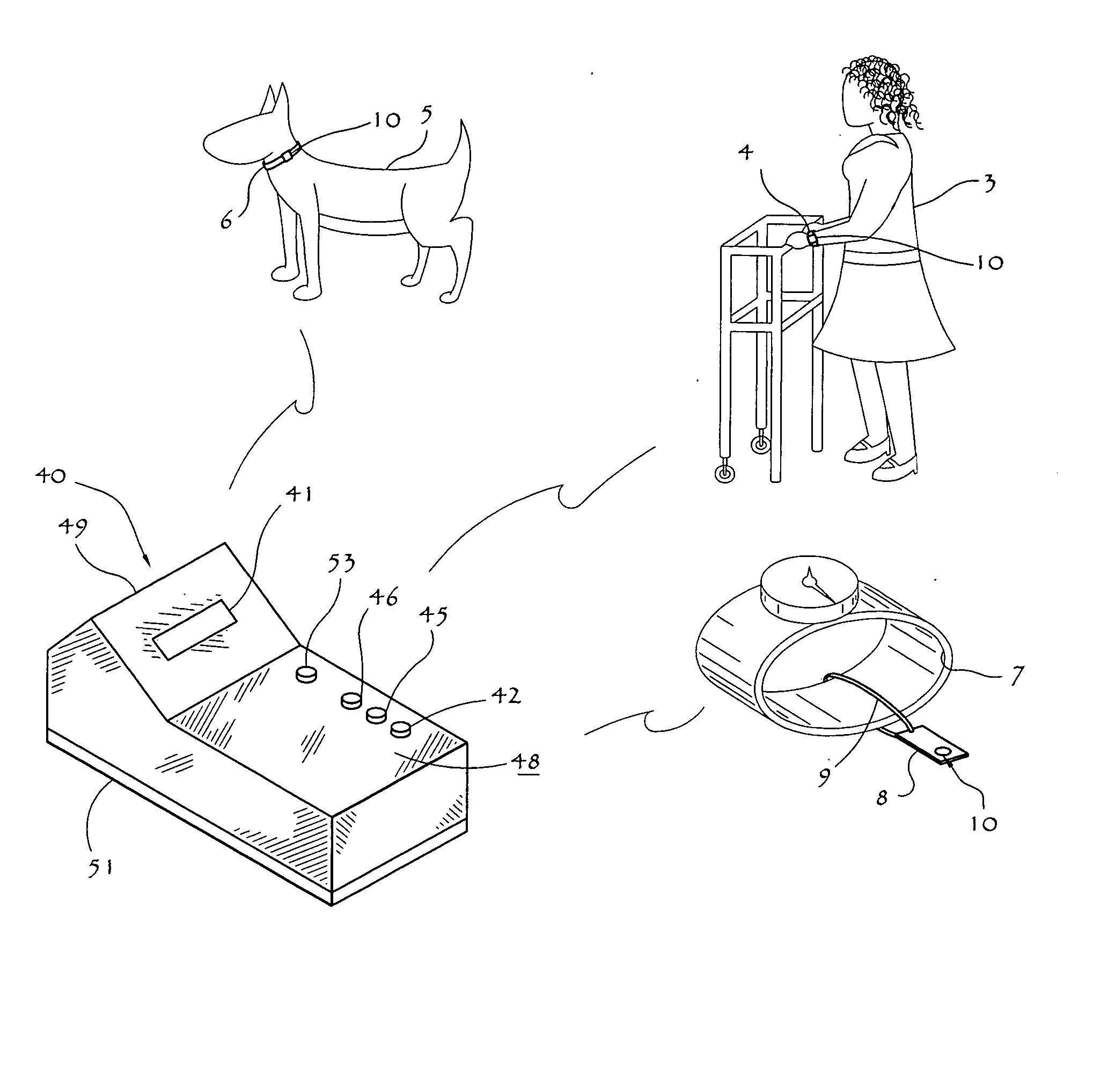
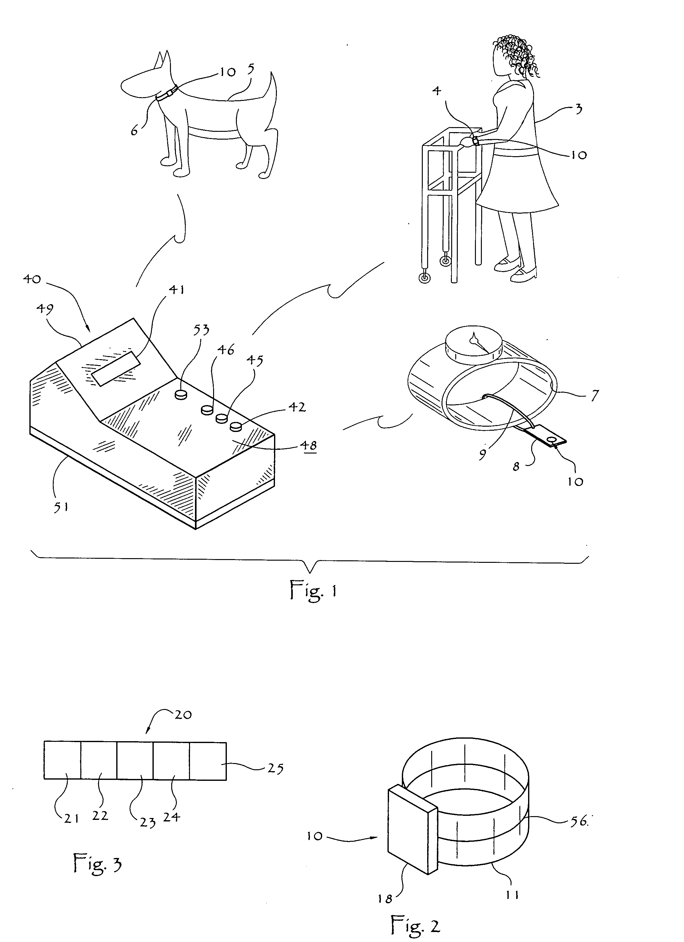
[0022] With reference now to the figures, and in particular to FIGS. 1-2, a general scheme of the present invention depicts multiple targets 1 being tracked by a single monitoring base unit 40 according to the present invention. The present invention has a wide variety of applications, some of which are depicted in FIG. 1, such as keeping track of ambulatory patients 3 at a nursing home or hospital, tracing livestock or pets 5 within a neighborhood (not shown), or tagging expensive merchandise 7 to assure it does not leave a retail premises without being purchased. One having ordinary skill in the art will recognize that other targets 1 may be monitored, with appropriate variations as described below, without departing from the spirit and scope of the present invention.

[0023] Transmitter 10 typically employs attachment means 11 appropriate to target 1. For example, as depicted in FIG. 2, transmitter 10 includes an elastic strap 11 forming a loop adapted to surround the arm for comf...


PUM


Abstract

A wireless electronic tracking system employs transmitters attached to moveable target items that send continuous analog radio frequency (RF) digitally-coded signals at prime number differentiated time intervals to a base receiver. The coded signals carry transmitter and base unit identifiers, low battery and attachment status information. The base unit periodically scans using an omnidirectional antenna to determine distance and azimuth for multiple active transmitters, alerting an operator to any status alerts, such as ‘out of range’ status determined by signal strength. The operator can switch to a higher gain, directional antenna to search for an errant target transmitter, or simply to check on the whereabouts of any given target item. Because the movable target items need only transmit, the transmitters can be physically diminutive and unobtrusive to the target wearer, making the system practical for tracking people (e.g. geriatric or juvenile, for assistance or to deter leaving group members behind), animals (e.g. pets, livestock) and even inventory (e.g. especially expensive items that shouldn't move from a given spot in a retail setting).

Description

BACKGROUND OF THE INVENTION [0001] 1. Field of the Invention [0002] This invention relates generally to wireless monitoring systems and particularly to such systems adapted to monitor the location of movable items such as people, animals or merchandise. More particularly, this invention relates to a wireless transmitter attached to each item and a base station monitoring multiple items, providing out of range alarms and doubling as a finding device. [0003] 2. Description of Related Art [0004] Geriatric patients often move about freely within the boundaries of a resident hospital, but some could endanger themselves and become lost and unable to find their way home if they wander outside the grounds. Likewise, pets straying too far from a home location sometimes get lost or stolen. Expensive retail merchandise susceptible to shoplifting can be spirited away and if small enough hidden in the thief's pocket or packages, thereby deterring thorough investigation based on suspicion alone. ...

Claims


Application Information

Patent Timeline
IPC IPC(8): G08B1/08G08B13/14G08B23/00G08B21/00G08B5/22
CPCG08B13/1427G08B21/0202G08B13/2462G08B13/2434
Inventor ELLIOTT, ROBERT ODELL
Owner ELLIOTT ROBERT ODELL
Why Eureka
Try Eureka