
Ink-jet head device, ink-jet device, and ink-supplying method of ink-jet head device

a head device and inkjet technology, applied in the direction of printing, other printing devices, etc., can solve the problems of large difference between the head and the ink tank, increase the amount of consumed ink, and increase so as to achieve suitable negative pressure and reduce the consumption of ink.

Inactive Publication Date: 2006-03-02
SHARP KK
View PDF10 Cites 17 Cited by
  • Summary
  • Abstract
  • Description
  • Claims
  • Application Information

AI Technical Summary

Benefits of technology

[0013] The present invention was made in view of foregoing problems, and it is an object of the present invention to realize an ink-jet head device with a main tank and a sub tank, in which the ink-jet head can maintain suitable negative pressure, and in which consumption of ink is reduced, and to realize an ink-jet device including the ink-jet head device, and an ink-supplying method for the ink-jet head device.

Problems solved by technology

In devices such as large ink-jet printers or large production devices using the ink-jet technology, the amount of consumed ink is inevitably increased, and accordingly large-capacity ink tanks are used.
In this case, the head difference between the ink tank and the ink-jet head varies widely according to how much ink is left, and it sometimes causes troubles.
For example, if the amount of remaining ink is large, the head difference between the ink tank and the ink-jet head becomes large, and accordingly applied pressure on the ink-jet head becomes large.
As a consequence, it becomes impossible to maintain enough negative pressure not to leak ink in the ink-jet head, with the result that ink may leak out of the ink-jet head.
As a consequence, the ink-jet head sucks air, with the result that ink cannot be jetted.
However, the above conventional structure in which the ink tank is located in the housing of the main body, and in which ink is supplied through a flexible conduit to the ink-jet head provided in the carriage poses the following problems.
Further, in larger devices, because the length of flexible conduits increases, this problem becomes more serious.
As the above example shows, in the conventional ink-jet recording device that has the ink tank outside the carriage and supplies ink through the flexible conduit, a problem occurs that more ink is consumed compared to an ink-jet device in which the ink tank is provided in a carriage.
Further, in the ink-jet device with two ink tanks (main tank and sub tank) as reported in the above Japanese Laid-Open Patent Publication No. 266734 / 2003, the problem of increased ink consumption also occurs because the flexible conduit connecting the main tank and the sub tank needs to be filled with ink.

Method used


Image

  • Ink-jet head device, ink-jet device, and ink-supplying method of ink-jet head device
  • Ink-jet head device, ink-jet device, and ink-supplying method of ink-jet head device
  • Ink-jet head device, ink-jet device, and ink-supplying method of ink-jet head device

Examples


Embodiment Construction

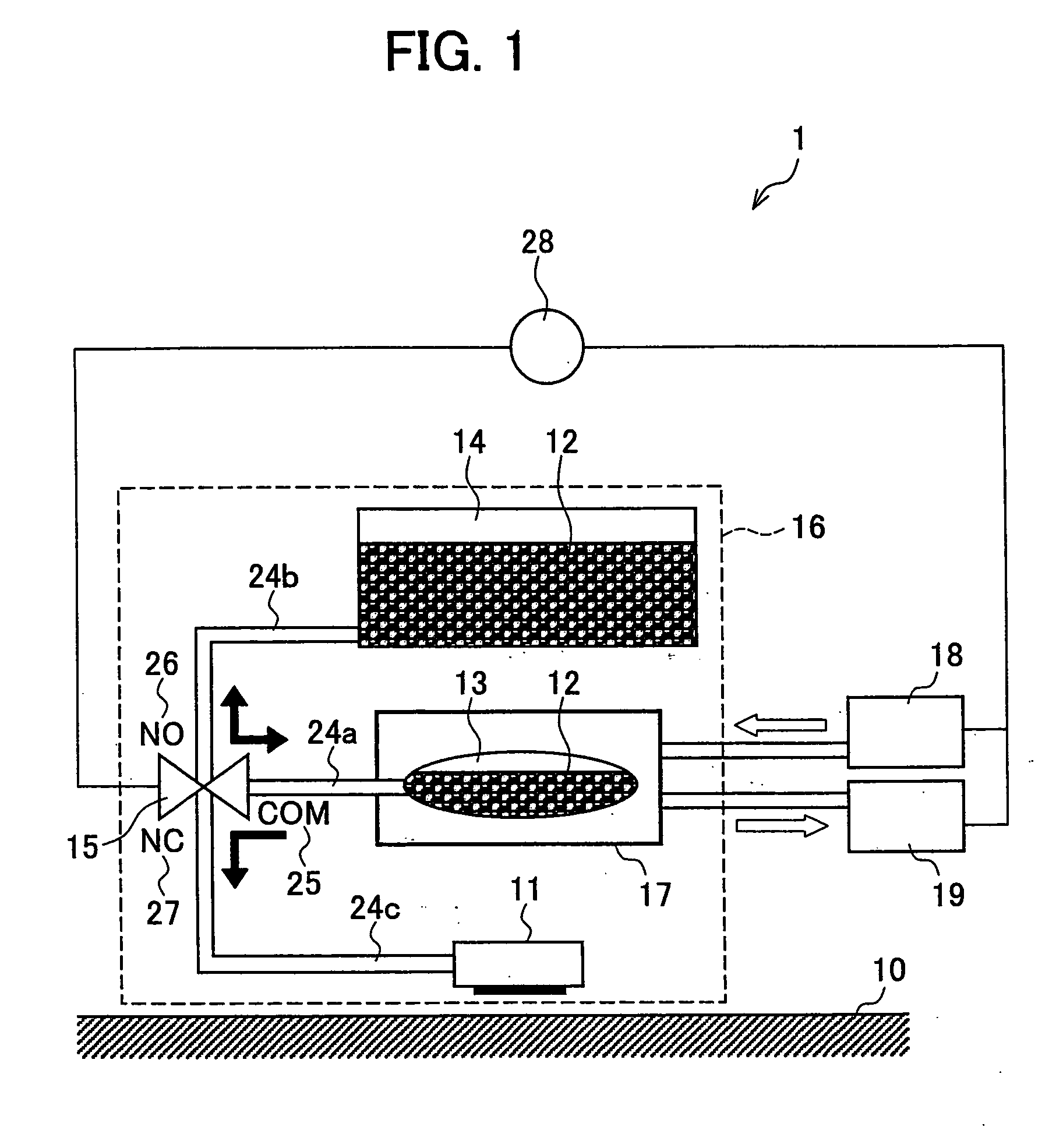
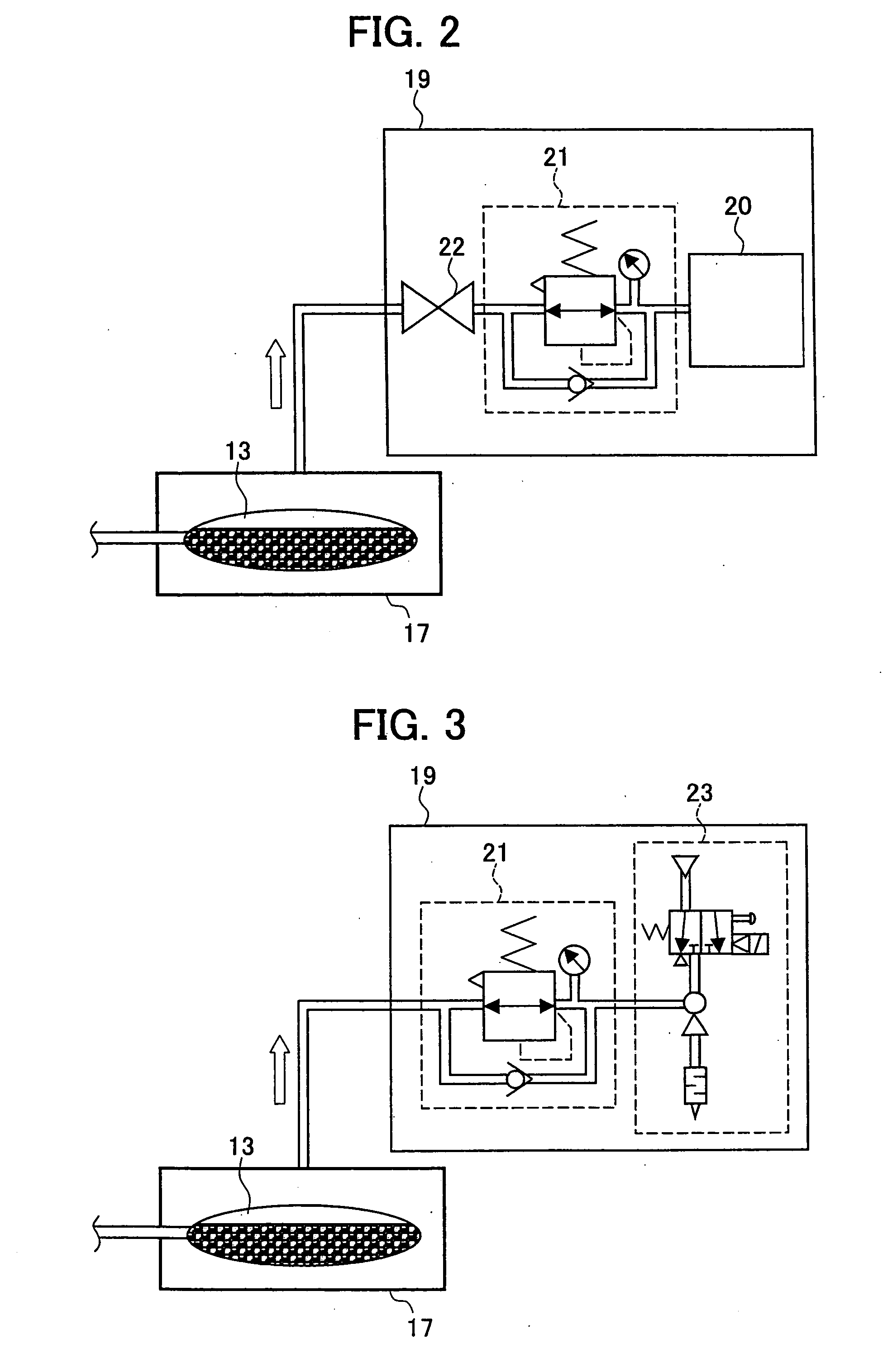
[0027] Embodiments of the present invention will be described below with reference to FIG. 1 through FIG. 4. Note that the present invention is not limited to these embodiments.

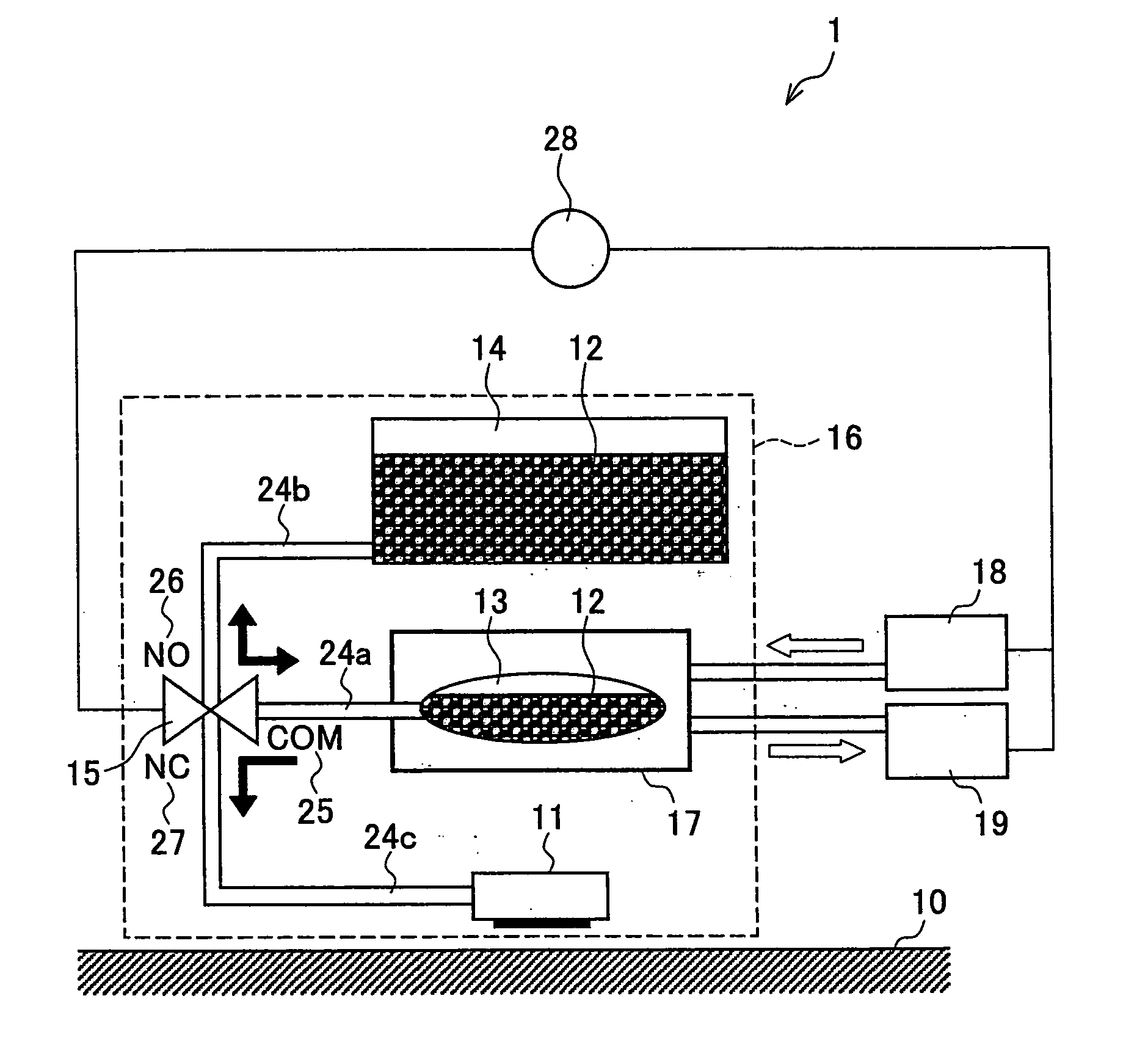
[0028]FIG. 1 relates to one embodiment of the present invention, schematically showing a main structure of an ink-jet head device 1 mounted in an ink-jet device. As shown in FIG. 1, main components of the ink-jet head device 1 of the present embodiment include an ink-jet head 11, a sub tank 13, a main tank 14, a three-way switching valve (flow path switching means; flow path switching unit) 15, ink conduits (three-way flow path) 24a, 24b, 24c, a movable carriage 16, relative positive pressure generating means (relative positive pressure generating unit) 18, negative pressure generating means (negative pressure generating unit) 19, and a controller (flow path controller, relative positive pressure controller, negative pressure controller) 28.

[0029] Here, the ink-jet head 11, the sub tank 13 and the main tank...


PUM


Abstract

In an ink-jet head device, a main tank, a sub tank and an ink-jet head are mounted in this order in a carriage, with the main tank placed at the top. The main tank, sub tank and ink-jet head are connected to one another by a three-way ink conduit. At a junction of the ink conduit is disposed a three-way switching valve, which selectively switch a path connecting the sub tank to the main tank and a path connecting the sub tank to the ink-jet head, without causing the ink-jet head and the main tank to communicate with each other. As a result, an ink-jet head device and an ink-supplying method are realized, in which the ink-jet head can maintain suitable negative pressure and in which consumption of ink is reduced.

Description

[0001] This Nonprovisional application claims priority under 35 U.S.C. § 119(a) on Patent Application No. 251059 / 2004 filed in Japan on Aug. 30, 2004, the entire contents of which are hereby incorporated by reference.FIELD OF THE INVENTION [0002] The present invention relates to an ink-jet head device for jetting ink to a medium, an ink-jet device, and an ink-supplying method used in the ink-jet head device. The present invention particularly relates to: an ink-jet head device including an ink tank, an ink-jet head, and a carriage; an ink-jet device using the ink-jet head device; and a method for supplying ink from the ink tank to the ink-jet head in the ink-jet head device. As used herein, the “ink” is not just limited to those used for printing or drawing on a medium like paper, but the term refers to fluids in general. BACKGROUND OF THE INVENTION [0003] Today, examples of devices using the ink-jet technology include ink-jet printers that jet ink on a medium like recording paper t...

Claims


Application Information

Patent Timeline
IPC IPC(8): B41J2/175
CPCB41J2/17596B41J2/175B41J2/17513B41J2/17523B41J2/17546
Inventor MUTOH, YOSHINORIHIGUCHI, KAORU
Owner SHARP KK
Learn More