Switching mode power supplies

a power supply and switching mode technology, applied in the direction of electric variable regulation, process and machine control, instruments, etc., can solve the problems of low switching operation frequency, low switching loss, and huge reduction of smps efficiency, so as to remove high frequency bursting

Active Publication Date: 2006-03-02
INFINEON TECH AG
View PDF14 Cites 51 Cited by
  • Summary
  • Abstract
  • Description
  • Claims
  • Application Information

AI Technical Summary

Benefits of technology

[0011] The invention thus makes it possible to determine the duty cycle and the frequency of a burst mode only from a feedback signal which conta

Problems solved by technology

However, when the load decreases and the switching cycle remains the same, the efficiency of the SMPS decreases tremendously, since power losses are almost entirely due to the switching losses, which in turn are almost exactly proportional to the number of switching operations the transistor performs.
Thus, in modes for which the power consumption of the load is low, the frequency of the switching operation is low, and thus the switching losses are low.
A disadvantage of this technique is that if the frequency of the switching operations decreases into the audible range, an audible noise is generated by the transfor

Method used


Image

  • Switching mode power supplies
  • Switching mode power supplies
  • Switching mode power supplies

Examples


first embodiment

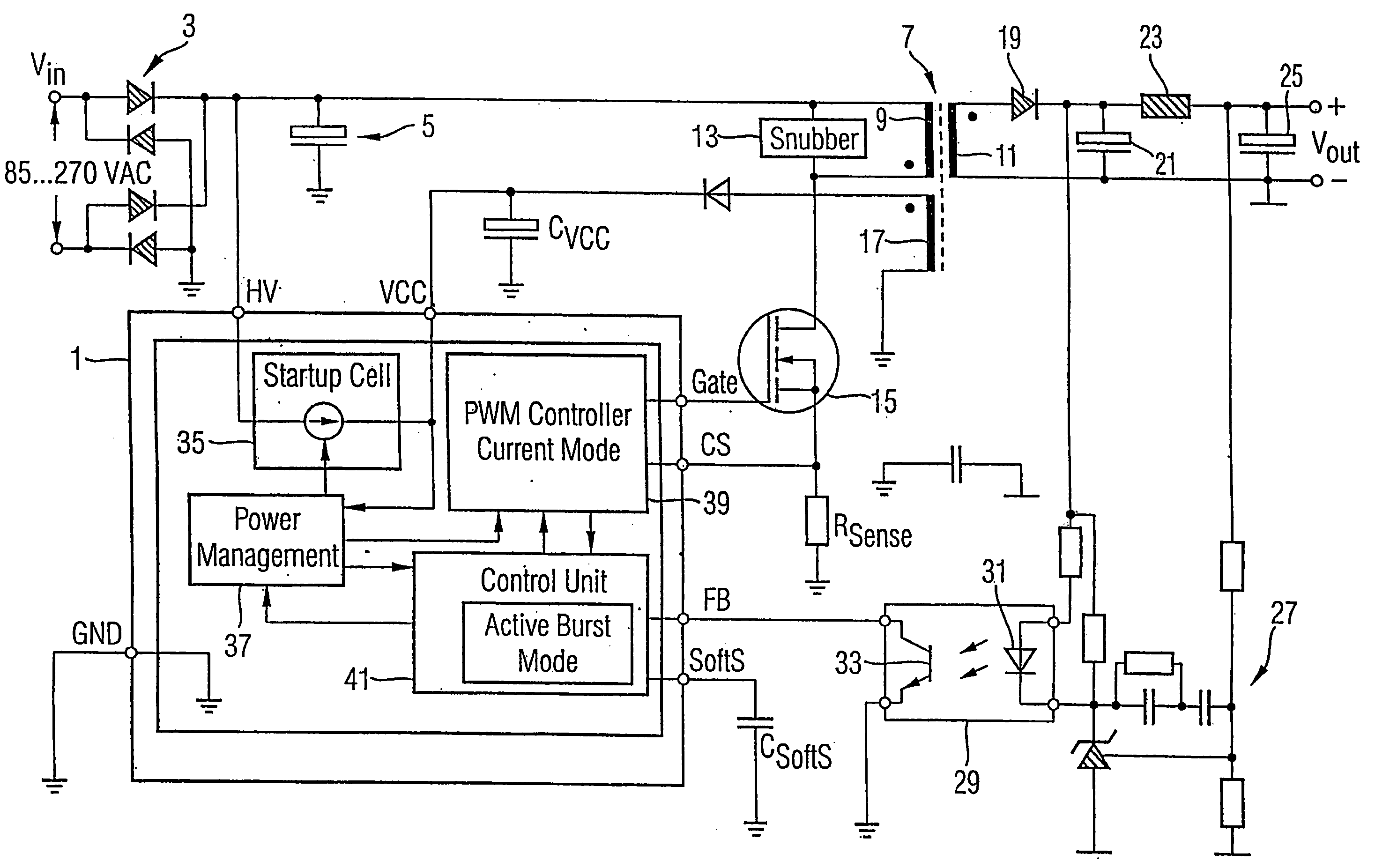
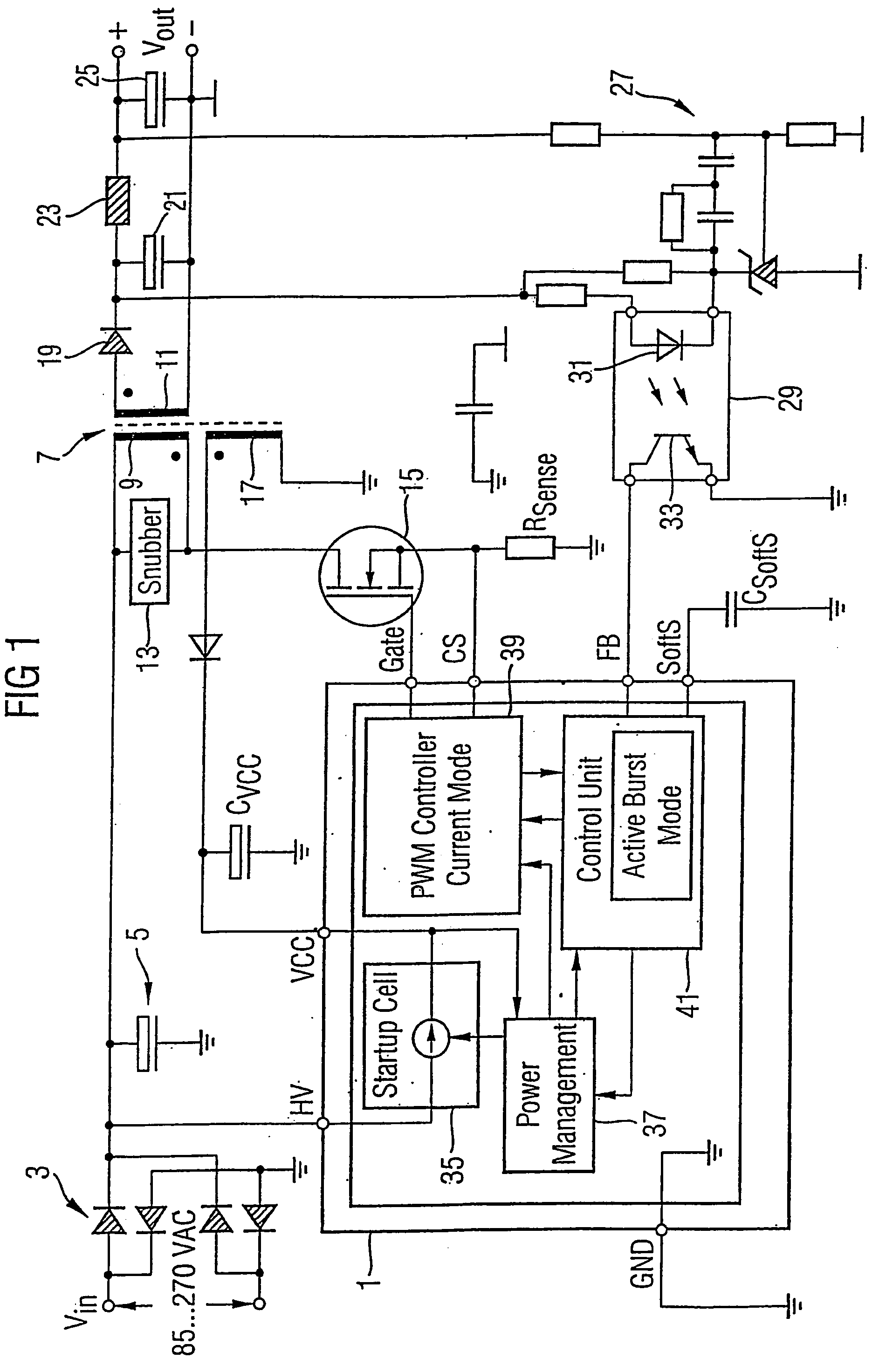
[0026]FIG. 1 shows schematically a power converter which is the invention. An AC voltage supply Vin is received at the left of the figure. Typically Vin is in the range 85 to 270V. It is rectified by a rectifier 3, and then passed to a smoothing capacitor 5. The DC voltage thus generated is fed to one input of a transformer 7 having a primary winding 9 and a secondary winding 11. A snubber 13 is connected between the two inputs of the primary winding 9, and the other common connection of the snubber 13 and primary winding 9 is connected to an input of a transistor 15. The gate of the transistor 15 is controlled by an output called “Gate” of a control system 1. The other side of the transistor 15 is connected to ground via a resistor Rsense. The voltage at one side of the resistor Rsense is an input CS to the control system 1. The control system 1 further receives an input HV from the rectifier 3 for powering the unit 1. When in standby mode, the input HV serves as a current source t...

second embodiment

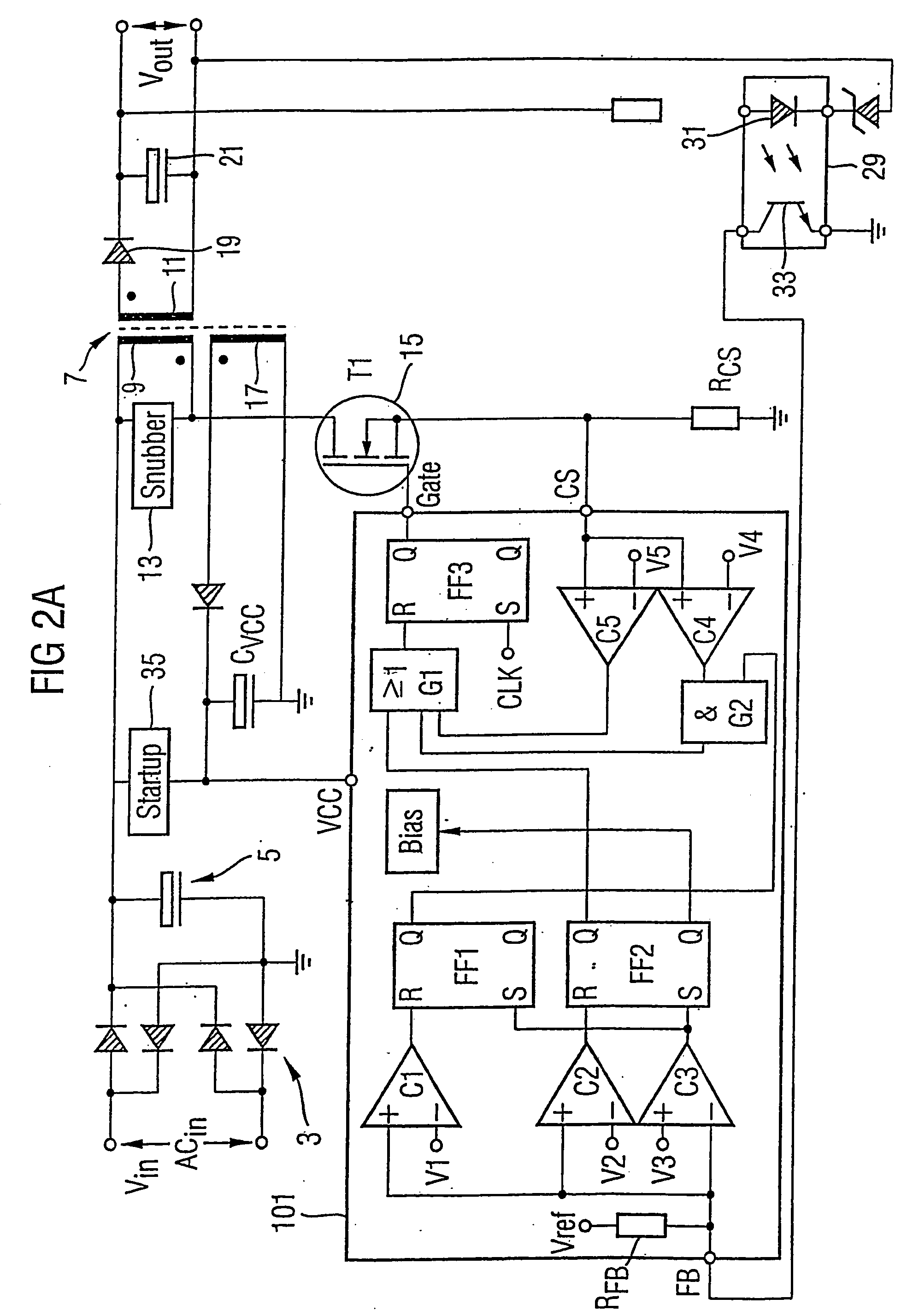
[0038]FIG. 2 (a) illustrates an embodiment in which the feedback signal is directly related to the power drawn by the load. FIG. 2 (b) shows an alternate implementation of the invention of FIG. 2 (a) in which the feedback signal is inversely related to the power drawn by the load. If the power consumption at Vout is decreasing, VFB (the feedback voltage) is increasing, and visa versa. Therefore, the relationship between the threshold voltages V1a, V2a and V3a is the inverse of the thresholds V1, V2 and V3 of the implementation of FIG. 2 (a) where the feedback signal is directly related to the power drawn by the load. The relationship is V3a>V2a>V1a. This same implementation method can be applied to circuits of FIGS. 6 and 7 described below. The signal curve for VFB is the inverse of those shown in FIGS. 3, 5 and 8 below. In the implementation of FIG. 2 (b), RFB (the feedback resistance) is acting as a pull-down resistor that can also be replaced by an active current sink.

[0039] The ...


PUM


Abstract

In a switching mode power supply, an input received from the secondary side of the transformer 7 and indicative of the power being drawn by the loads is used to control the timing of bursts. The input is compared with two threshold different threshold values V2, V3, and switching is enabled if the input rises above a first higher threshold value V2, and disabled if it falls below a second lower threshold value V3. A memory device FF1 controls a current limitation circuit which limits currents in the primary of the transformer when the switching mode power supply is operating in the burst mode.

Description

FIELD OF THE INVENTION [0001] The present invention relates to switching mode power supplies (SMPS), and in particular to a control circuit for a SMPS, to a SMPS itself, to apparatus powered by and incorporating the SMPS and to methods performed by the SMPS and the control circuit. BACKGROUND OF THE INVENTION [0002] Switching mode power supplies are being increasingly used in many domestic and industrial applications. Apparatus such as televisions or computer monitors operate in one of a number of states or modes. For example, a first “off” mode occurs when there is no power being supplied to the apparatus; a second “on” mode occurs when the device is switched on and operating normally; and a third mode, referred to as a “standby mode”, occurs when the device is to remain powered but with reduced functions and reduced power consumption. In the case that the apparatus is a television, for example, the standby mode may, for example, be a mode in which the television is not displaying ...

Claims


Application Information

Patent Timeline
IPC IPC(8): H02M3/335
CPCH02M3/33523Y02B70/16H02M2001/0032Y02B70/10H02M1/0032
Inventor FAHLENKAMP, MARCGONG, XIAO WUZOELLINGER, HARALD
Owner INFINEON TECH AG
Why Eureka
Try Eureka