
Transport aid for wheeled support apparatus

a technology for supporting devices and transportation aids, which is applied in the field of transportation and/or lifting devices or aids, and can solve the problems of difficult bed maneuvering via the device, functional restraining or limiting the “length” of the device, and cumbersome and difficult to mov

Active Publication Date: 2006-03-02
NUSTAR
View PDF21 Cites 25 Cited by
  • Summary
  • Abstract
  • Description
  • Claims
  • Application Information

AI Technical Summary

Benefits of technology

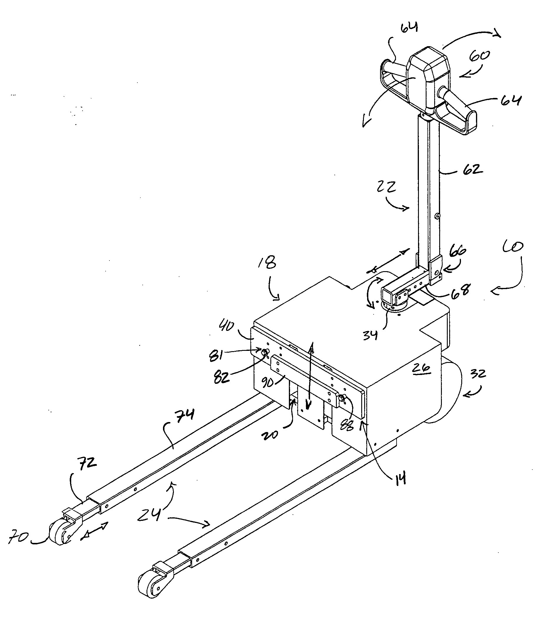
[0008] The subject transport, lifting or moving apparatus is an electrically powered motive device that is used to move wheeled support platforms, more particularly, hospital beds, stretchers, gurney, etc. The purpose of using a motorized moving device to move such items is to: (1) prevent the operator from injuring him / herself by over exerting their body; (2) prevent him / her from injuring others; and, (3) reduce the number of people required to move the transportable item for which moving or transport is sought.
[0009] An intuitive control is provided as part of a handle assembly of the device for user manipulation in furtherance of moving or transporting the bed, or bed and patient, throughout the health care facility. The further the lever is depressed, the faster the device will travel. To go in reverse, an operator reverses the lever direction, again, the further the lever is depressed, the faster the device / combination will travel.
[0010] The subject device further includes guide arms, more particularly, a pair of telescoping steering rails which, first provide stability for the device when there is no bed engaged, and, second, provide wheeled support at the far end of the bed (i.e., opposite the lifting mechanism) to facilitate steering of the unit. Having wheeled support at the far end of the bed prevents the bed from wanting to swing outward when it is being turned around corners, thus increasing the easy maneuverability of the device in combination with the bed for transport.
[0011] The subject device is especially advantageous in that it substantially fits below or under the bed for which transport is sought. Generally, the overall length of the device in combination with the bed is only a few inches greater than the length of the bed itself. This is particularly critical for a bed transported using the subject device to fit most elevators, and to permit 360 degree rotation and general maneuverability in tight areas often encountered in health care / hospital environments or settings.
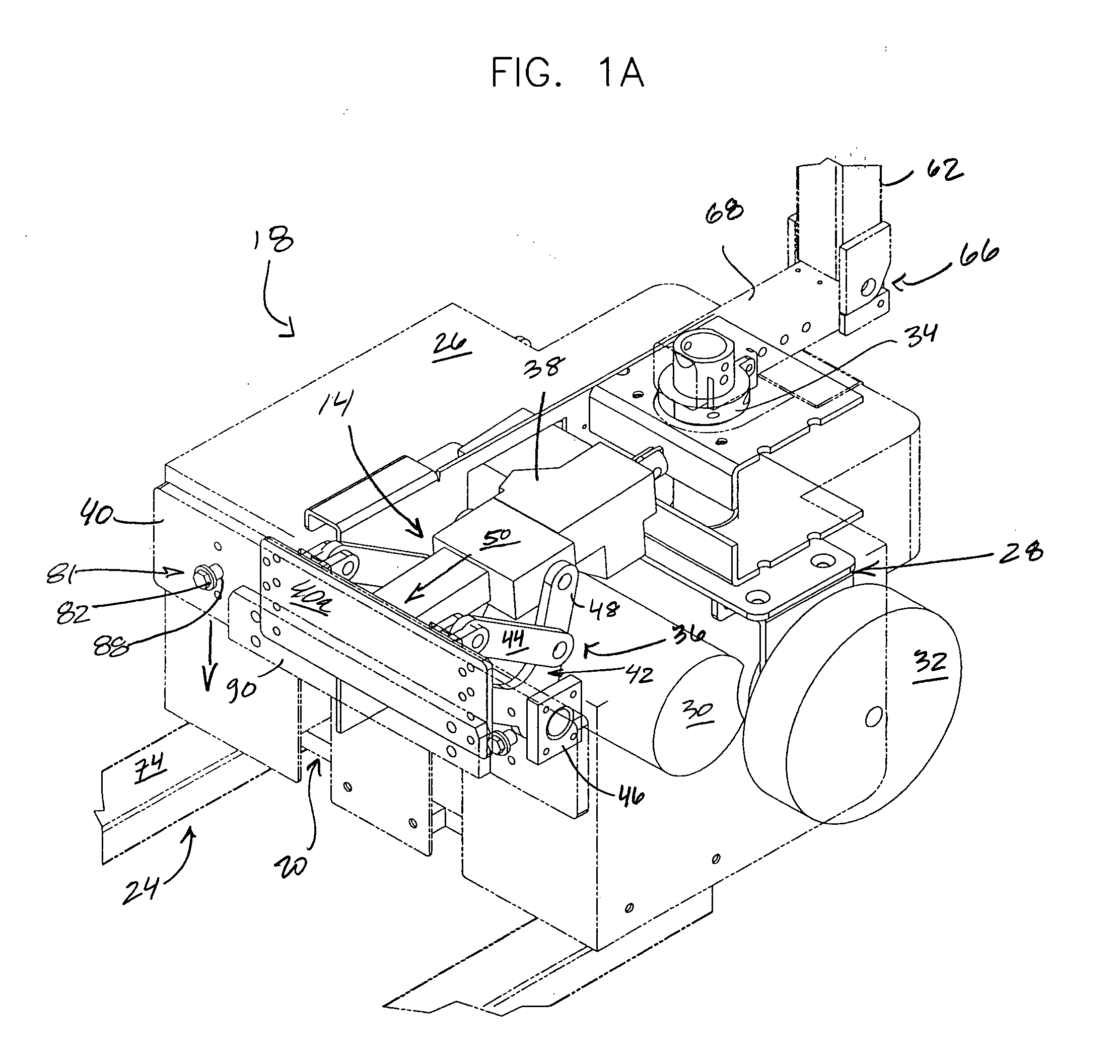
[0013] As will be more fulled developed and described, to move a support structure equipped with wheels, one of two pairs thereof are positioned for receipt on / in on the wheel trap assemblies of the transporter. User actuation of a lifting mechanism raises the trap assemblies, thereby capturing the wheels therein, and thereafter lifts an end of the wheeled support apparatus. By lifting a pair of the bed's wheels slightly off the ground, the wheels of the pair are effectively removed (i.e., operably or functionally removed), and are replaced or substituted with a motorized drive wheel, or drive wheel assembly, of the subject device. By this arrangement, the bed and the subject device achieve a very secure weight bearing interface, each essentially integrated or united into a single driven assembly which provides for supreme maneuverability.

Problems solved by technology

Especially challenging for moving about are wheeled support platforms characterized by at least one pair or set of casters, for example, hospital beds which are particularly cumbersome and difficult to move or generally transport within a healthcare facility or the like.
In addition to a generally weak interface between the device and the bed (i.e., the bed is easily detachable from the clamps), bed maneuvering via the device is difficult due in part to minimal power and / or traction, and a general device configuration which results in a functionally restraining or limiting “length” for the device.
Such device shortcomings, if not prohibitive, make bed transport up / down ramps commonly found in health care facilities difficult, and elevator loading and unloading burdensome.
Generally, such devices have ample power, however, the device, with bed in tow, drives like a car pulling a trailer, making it difficult to generally maneuver the combination, and more particularly, making it nearly impossible to back the unit up as is frequently required in the course of a transport operation.
Furthermore, the bed and the device together are far too long in length to fit into elevators, as well as to maneuver some of the commonly encountered ramps which are configured in a switch-back arrangement.

Method used


Image

  • Transport aid for wheeled support apparatus
  • Transport aid for wheeled support apparatus
  • Transport aid for wheeled support apparatus

Examples


Embodiment Construction

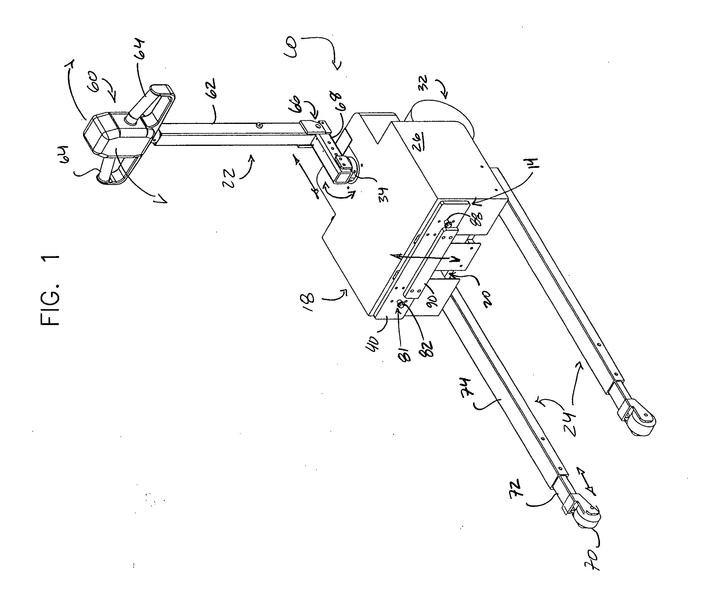
[0026] As a preliminary matter, the transport apparatus 10 of the subject invention is generally shown in FIG. 1, and more particularly shown in FIGS. 2, 3, 5&6 equipped with bed support structures 12, each of which is adapted, or readily adaptable for receipt and retention of a portion of a bed or other such structure for which transport is sought. Among other things, a lifting assembly 14 of the apparatus of the subject invention is generally shown in FIG. 1A, with FIGS. 7 & 8 illustrating features and elemental interrelationships of a wheel trap assembly 16 of the subject invention, more particularly, the trap assembly of the bed support structure of FIG. 2. As should be readily appreciated with reference to the figures, and as will be further developed, the subject transport apparatus advantageously, but not necessarily, has associated with it a modularity, that is to say, the apparatus of FIG. 1 may be selectively equipped, by various means illustrated and otherwise generally k...


PUM


Abstract

A self-propelled transport aid for wheeled structures is advantageously provided. The transport aid generally includes a chassis, a lift assembly operatively supported thereby, and preferably a wheel capturing apparatus operatively united with the lift assembly. The wheel capturing apparatus has a first configuration for receipt of a wheel upon a wheel landing of the apparatus, and a second configuration for retention of the wheel received upon the wheel landing in the first configuration, wherein the first configuration of the wheel capturing apparatus is associated with a down position thereof. Alternate means for receiving and retaining a portion of a wheeled structure are further disclosed.

Description

[0001] This is a regular utility application filed under 35 U.S.C. §111(a) claiming priority under 35 U.S.C. §119(e)(1), of provisional application Ser. No. 60 / 574,338 having a filing date of May 25, 2004.TECHNICAL FIELD [0002] The present invention generally relates to transport and / or lifting devices or aids, more particularly, to a transport device for receipt of a portion of a wheeled support platform, for instance, hospital beds, stretchers, gurney, etc., more particularly, a frame member or ground engaging wheel thereof. BACKGROUND OF THE INVENTION [0003] Wheeled support apparatuses or platforms of a variety of sizes and shapes are known to be available for the transport of persons, equipment, goods, etc., from one location to another. In furtherance of eliminating, at least minimizing, the strain and pain of manually pushing or pulling such wheeled support platforms, a variety of lifting, moving and / or transport devices are known to be available. Especially challenging for mo...

Claims


Application Information

Patent Timeline
Patent Type & Authority Applications(United States)
IPC IPC(8): B66F9/14A61G7/08B66F5/00B66F9/075B66F9/12
CPCB62B3/0612A61G7/08
Inventor SCHUCHARDT, PETER W.
Owner NUSTAR
Learn More