Parasitic mobility in dynamically distributed sensor networks

a sensor network and dynamic mobility technology, applied in the field of distributed, wirelessly networked collection of sensors, can solve the problems of locomotion cost, node size and power consumption, and difficulty in manual replacement of batteries or maintaining all nodes

Active Publication Date: 2006-03-02
MASSACHUSETTS INST OF TECH
View PDF5 Cites 156 Cited by
  • Summary
  • Abstract
  • Description
  • Claims
  • Application Information

AI Technical Summary

Benefits of technology

[0038] Parasitic mobility may also be used to advantage in connection with nodes without sensors—e.g., to move wireless relay nodes to locations where they can route messages through gaps in network coverage. In addition, the host that is used to provide mobility to a node may take a variety of forms, including a vehicle, a human, an animal, or any other physically moving object or fluid that can carry a node from place to place.

Problems solved by technology

But the creation of mobile nodes is not without a price.
Locomotion is costly in terms of node size and power consumption.
In dense sensor systems, due to the large quantity of nodes and distributed coverage, it is difficult to manually replace batteries or maintain all nodes.
Zurich, Switzerland: Springer-Verlag] have explored using robots to maintain distributed networks, but this is difficult to implement over large, unrestricted environments.
Additionally, the added intelligence and processing power required for a node to successfully navigate in an arbitrary environment further increases the power and size requirements of each node.
Large nodes, in physical size, complexity, cost, and power consumption, prevent the sensor network from being implanted in most environments.
As a result, pens generally cover large areas over time, and due to their unlikelihood of being returned, people usually have redundant supplies of pens.
Although it seems possible that this system can be deployed, according to the National Severe Storms Laboratory [see The National Severe Storm Laboratory, FAQ. http: / / www.nssl.noaa.gov / faq / vortex.shtml], such devices have not been built.
They have experimented with a large barrel-sized sensor device called TOTO (TOtable Tornado Observatory), but these tests have yielded only minimal success.

Method used


Image

  • Parasitic mobility in dynamically distributed sensor networks
  • Parasitic mobility in dynamically distributed sensor networks
  • Parasitic mobility in dynamically distributed sensor networks

Examples


Embodiment Construction

[0057] Overview

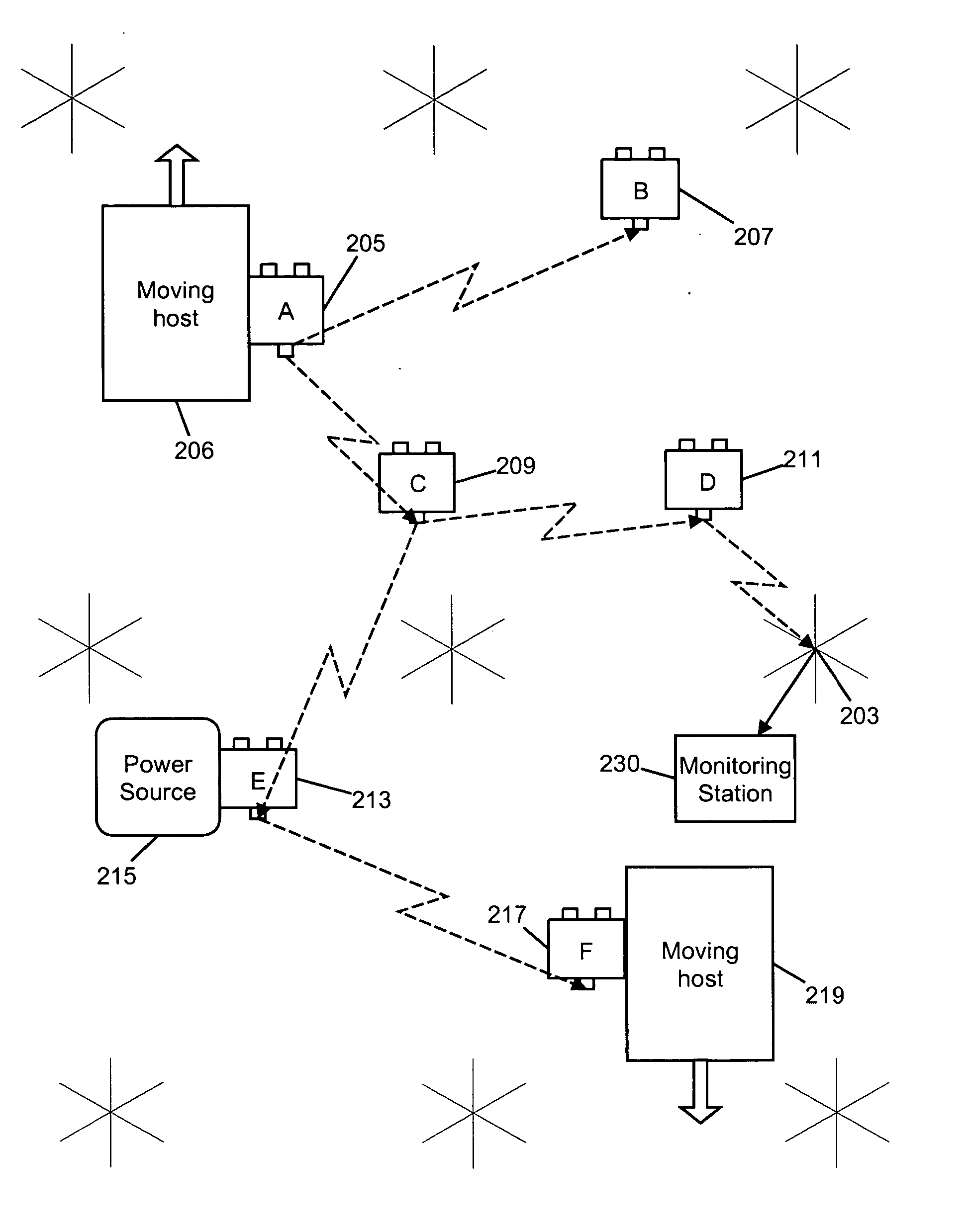
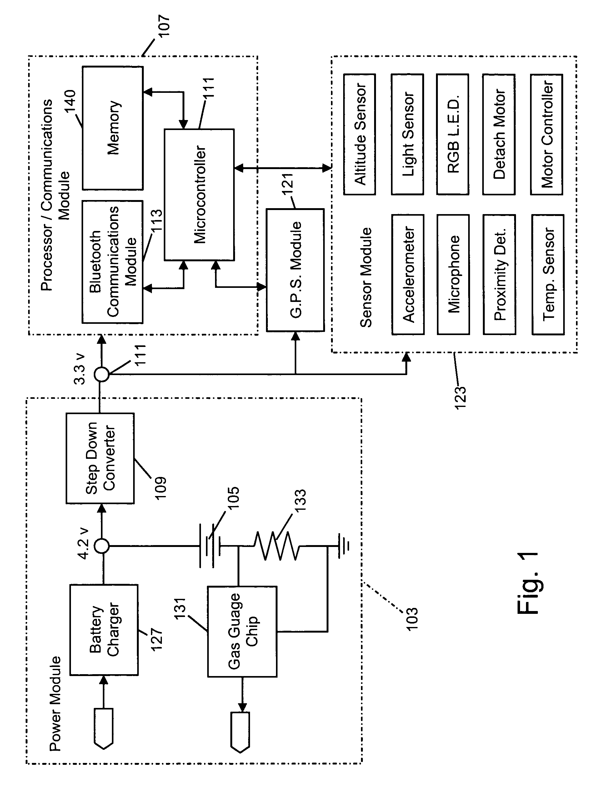
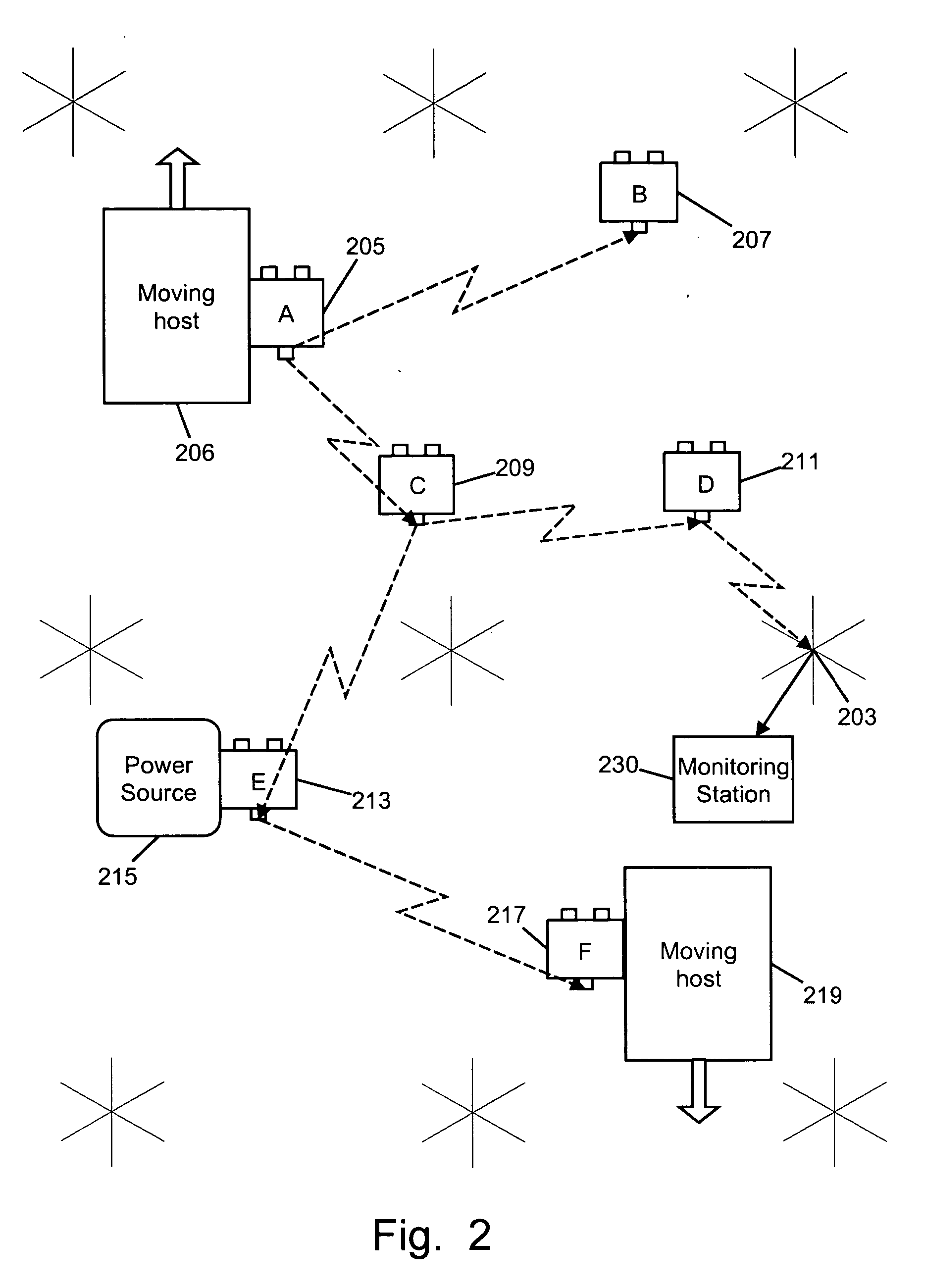
[0058] The preferred embodiment of the invention consists of a wireless network of sensing nodes which are carried by moving hosts to desired locations. Each sensing node includes an internal power source, one or more sensors, a wireless communications unit for exchanging information with other nodes, and a supervisory control processor. A block diagram of a single node is seen in FIG. 1, and a network of such nodes is shown in FIG. 2.

[0059] In the description that follows, each sensing node will frequently be referred to as a “paramor,” a name given to a parasitically mobile node (an anagram for PARAsitic MObility Research).

[0060] As seen in FIG. 1, each sensing node in the network contains all the necessary elements for processing, communication, data storage and includes a location system, a suite of sensors, and an onboard rechargeable power source. The power module seen at 103 supplies power to the other components from a rechargeable battery 105. A processing...


PUM


Abstract

A distributed sensor networks employing mobile sensing nodes that are carried to desired locations by attaching themselves to moving hosts and detaching themselves when the host arrives at the desired location or is moving away from the desired location. Each sensing node may carry a plurality of environmental sensors and communicates with nearby sensing nodes using a short range wireless link. The node further carries a location sensing mechanism and uses either active, passive or attractive means to attach itself to a moving host.

Description

FIELD OF THE INVENTION [0001] This invention relates generally, but in its broader aspects not exclusively, to distributed, wirelessly networked collections of sensors. BACKGROUND OF THE INVENTION [0002] We are at a point in time where advances in technology have enabled production of extremely small, inexpensive, and wirelessly networked sensor clusters. We can thus implant large quantities of sensors into an environment, creating a distributed sensor network. Each individual node in the network can monitor its local space and communicate with other nodes to collaboratively produce a high-level representation of the overall environment. By using distributed sensor networks, we can sculpt the sensor density to cluster around areas of interest, cover large areas, and work more efficiently by filtering local data at the node level before it is transmitted or relayed peer-to-peer [see Meguerdichian, S., et al. Localized algorithms in wireless ad-hoc networks: location discovery and sen...

Claims


Application Information

Patent Timeline
Patent Type & Authority Applications(United States)
IPC IPC(8): H04B1/034G08B1/08G08C19/16
CPCG08B25/009H04B1/3827H04B1/034
Inventor PARADISO, JOSEPH A.LAIBOWITZ, MATHEW JOEL
Owner MASSACHUSETTS INST OF TECH
Why Eureka
Try Eureka