Liquid ejection head and liquid ejection apparatus

a liquid ejection and liquid ejection technology, which is applied in the direction of printing and inking apparatus, etc., can solve the problems of reducing the size of the actuator provided on the pressure chamber, deteriorating the performance of the actuator, and difficulty in achieving the high nozzle density that is required for high-speed printing, etc., and achieves favorable liquid ejection. , the effect of increasing the resonance frequency

Inactive Publication Date: 2006-03-09
FUJIFILM CORP
View PDF7 Cites 37 Cited by
  • Summary
  • Abstract
  • Description
  • Claims
  • Application Information

AI Technical Summary

Benefits of technology

[0015] In other words, the relationship between the inertance Mn of the nozzle and the inertance Ms of the supply side flow passage satisfies Mn>Ms, and the resonance frequency between the compliance of the pressure chamber and the inertance of the nozzle and supply side flow passage can be increased. Therefore, liquid ejection can be performed using the resonance between the compliance of the pressure chamber and the inertance of the nozzle even when highly viscous ink, with which the resonance between the compliance of the pressure chamber and the inertance of the nozzle attenuates rapidly, is used.
[0046] According to the present invention, a nozzle and a supply side flow passage are constituted such that the inertance Mn of the nozzle and the inertance Ms of the supply side flow passage satisfy a relationship of Mn>Ms, and the resonance between the compliance of the pressure chamber and the inertance of the supply side flow passage is used to control liquid ejection. In so doing, the resonance frequency can be increased, and favorable liquid ejection can be realized even when using a highly viscous liquid, with which this resonance attenuates rapidly.

Problems solved by technology

When the size of the pressure chamber is reduced, the size of actuator provided on the pressure chamber also decreases, which may lead to deterioration in the actuator performance.
When the nozzle diameter is widened, it becomes difficult to achieve the high nozzle density that is required for high-speed printing.
Moreover, the nozzles that are in practical use at present are very short, and if the nozzle length were reduced even further, the rigidity of the ejection surface would decrease, causing a possible deterioration in the ejection stability.
Further, when the ink viscosity increases, ink cannot be ejected unless pressure above a certain level is applied, and hence it becomes impossible to eject smaller ink droplets than the ink droplet amount corresponding to this pressure.
As a result, the size of the ink droplets ejected cannot be made small.
However, when the ink viscosity increases, it may be impossible to maintain a predetermined ejection frequency.

Method used


Image

  • Liquid ejection head and liquid ejection apparatus
  • Liquid ejection head and liquid ejection apparatus
  • Liquid ejection head and liquid ejection apparatus

Examples


application examples

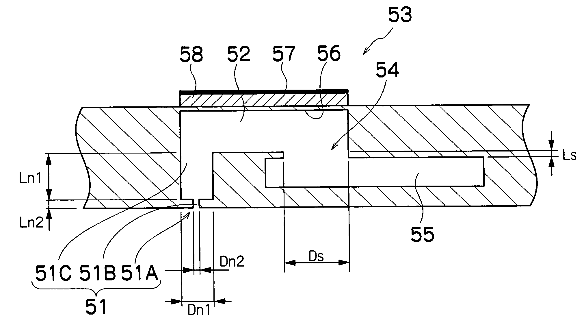
[0173] Next, application examples of the ink chamber unit 53 provided in the print head 50 will be described.

[0174]FIG. 15 is a sectional view showing the solid structure of the ink chamber unit 53 in an application example of the present embodiment.

[0175] As shown in FIG. 15, an elastic member 300 is provided at the supply port 54. The elastic member 300 has a substantially identical size to the supply port 54, and is provided with an opening (hole) 302 in the substantially central portion thereof. A diameter Ds′ of the opening 302 is considerably smaller than the width Ds of the supply port 54. Cuttings extending radially from the opening 302 are provided in the elastic member 300 so that the sectional area of the opening 302 increases when pressure is applied.

[0176] The elastic member 300 has an anistropic property so that the elastic member 300 deforms toward the common flow passage 55 side when pressure is applied in the direction denoted with an arrow K, but does not deform...


PUM


Abstract

The liquid ejection head comprises: a nozzle through which liquid is ejected, the nozzle having an inertance Mn; a pressure chamber which accommodates the liquid to be ejected through the nozzle; a pressurizing device which applies pressure to the liquid accommodated in the pressure chamber by deforming the pressure chamber to eject the ink from the pressure chamber; and a supply side flow passage which communicates with the pressure chamber and supplies the liquid to the pressure chamber, the supply side flow passage having an inertance Ms smaller than the inertance Mn of the nozzle.

Description

BACKGROUND OF THE INVENTION [0001] 1. Field of the Invention [0002] The present invention relates to a liquid ejection head and a liquid ejection apparatus, and more particularly to the structure of a liquid ejection head used in an inkjet recording apparatus or the like. [0003] 2. Description of the Related Art [0004] As an example of an image forming apparatus, there is known an inkjet recording apparatus which has an inkjet head (ejection head) having disposed multiple nozzles (ejection elements) therein, and forms an image on a medium (ejection receiving medium) by ejecting ink from the nozzles while relatively moving the inkjet head and the medium. [0005] For an ink ejection method in an inkjet head of an inkjet recording apparatus, there is known a piezoelectric method where a diaphragm (pressure plate) constituting a part of a pressure chamber is deformed by deformation of a piezoelectric element to change the volume of the pressure chamber, ink is introduced from an ink supp...

Claims


Application Information

Patent Timeline
Patent Type & Authority Applications(United States)
IPC IPC(8): B41J2/045
CPCB41J2/14233B41J2002/14459B41J2202/21B41J2202/20B41J2202/11
Inventor MATAKI, HIROSHI
Owner FUJIFILM CORP
Why Eureka
Try Eureka