Display control circuit, display control method, and liquid crystal display device

a display control and control circuit technology, applied in static indicating devices, non-linear optics, instruments, etc., can solve the problems of complicated control, burden on users, and difficulty in smoothly displaying the motion of objects

Inactive Publication Date: 2006-03-16
JAPAN DISPLAY CENTRAL CO LTD
View PDF6 Cites 54 Cited by
  • Summary
  • Abstract
  • Description
  • Claims
  • Application Information

AI Technical Summary

Benefits of technology

[0015] The object of the present invention is to provide a display control circuit, a display control method and a liquid crystal display device, which can vary the brightness of a display panel in a linear fashion in relation to a dimmer signal from outside in blink-driving of a backlight.

Problems solved by technology

In the meantime, since the liquid crystal display panel is a hold-type display device that holds a display state until updating of image data, it is difficult to smoothly display the motion of an object, owing to the effect of retinal persistence occurring on a viewer's vision in moving-image display.
However, the black display state that is obtained by the black insertion driving is not the perfect black, which would be obtained, for example, when the backlight is turned off.
However, even if the duty ratio of the backlight is varied by the dimmer signal, the backlight is turned off during the holding period of the pixel voltage for gradation display or turned on during the holding period of the pixel voltage for black insertion, owing to the effect of the black insertion ratio and black insertion timing on the liquid crystal display panel side, and the brightness of the liquid crystal display panel does not linearly vary in relation to the variation in duty ratio of the backlight.
In this case, however, the provision of the external signal source is a burden on the user, and a very complicated control is required.

Method used


Image

  • Display control circuit, display control method, and liquid crystal display device
  • Display control circuit, display control method, and liquid crystal display device
  • Display control circuit, display control method, and liquid crystal display device

Examples


Embodiment Construction

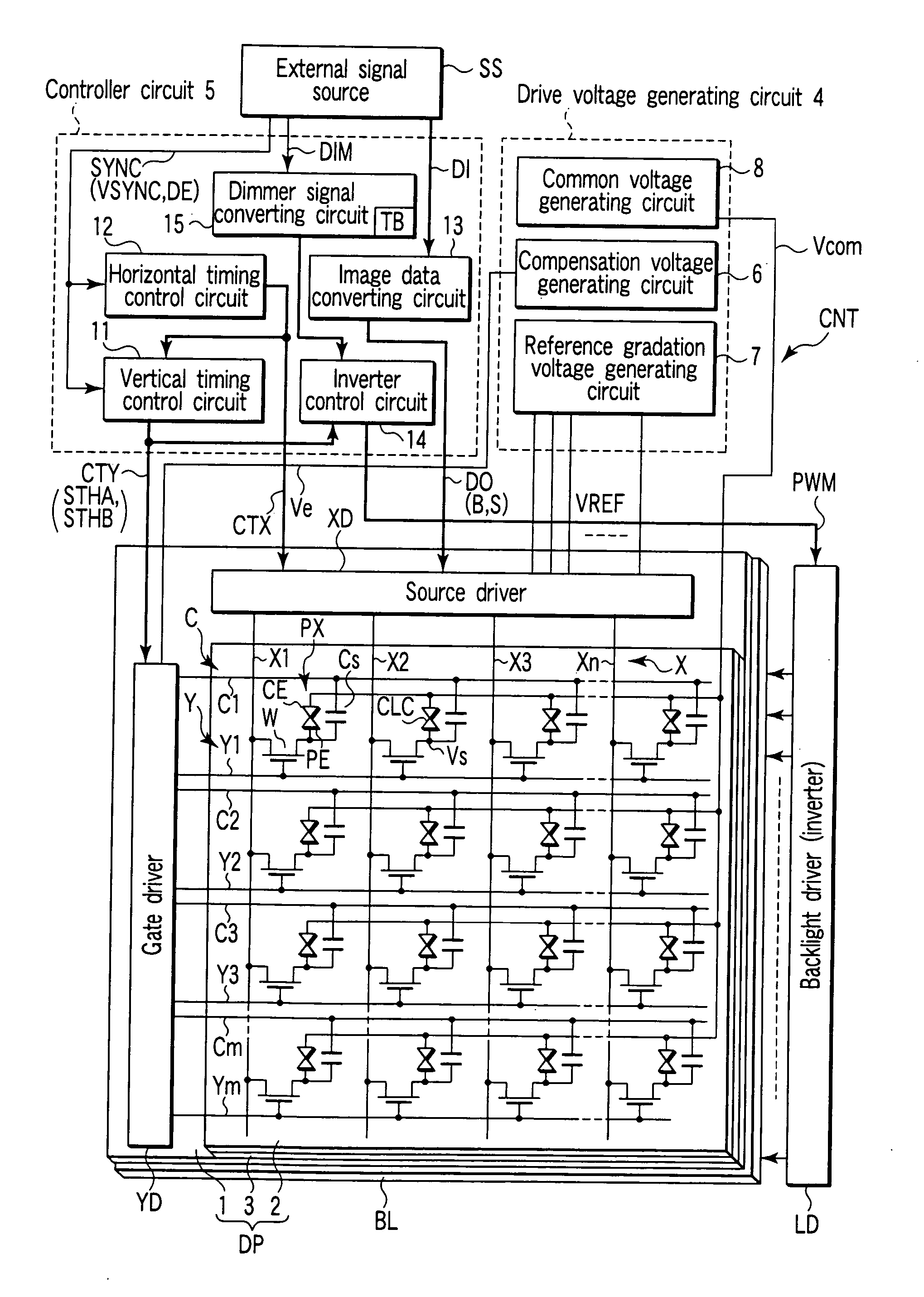
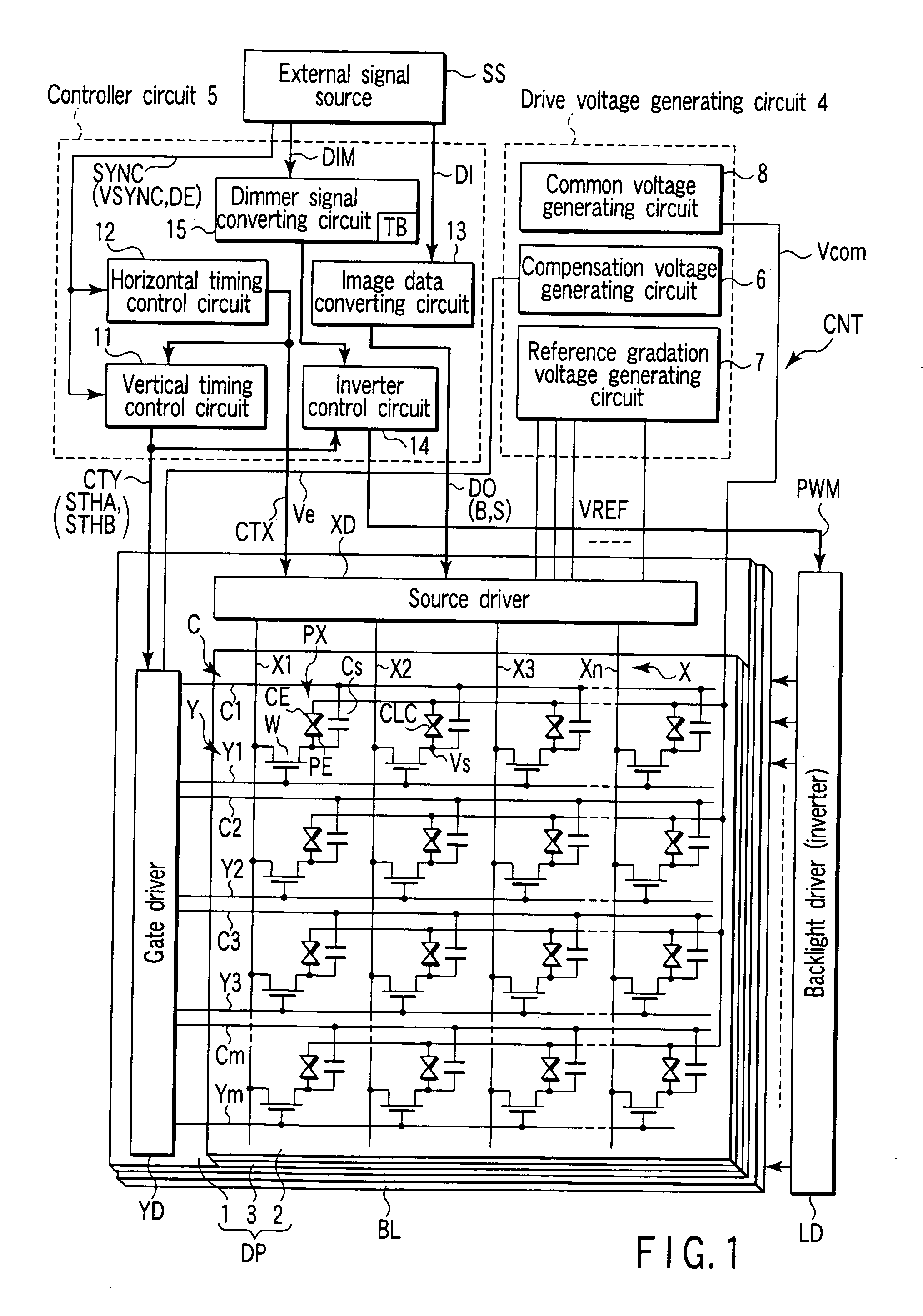
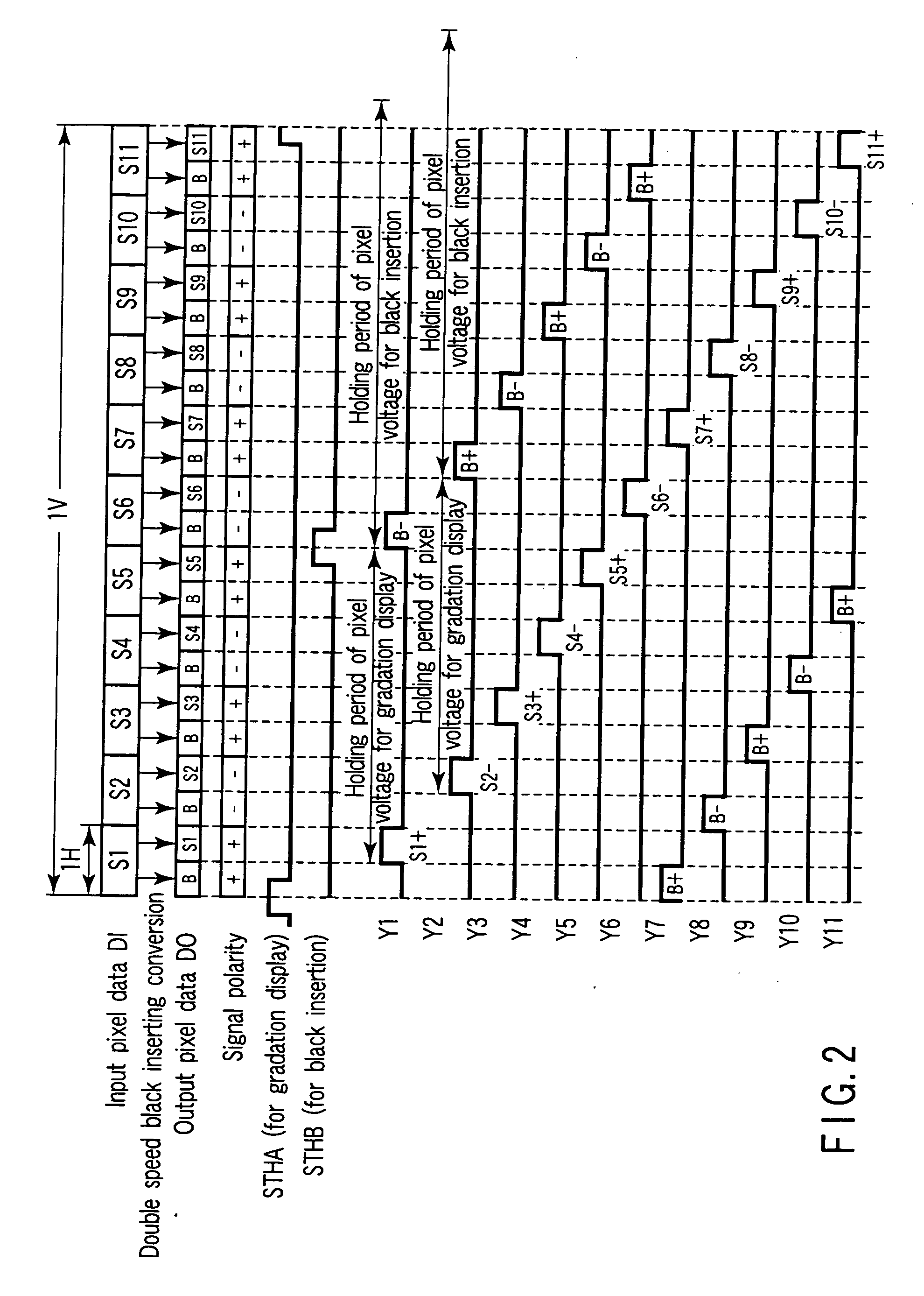
[0032] A liquid crystal display device according to an embodiment of the present invention will now be described with reference to the accompanying drawings. FIG. 1 schematically shows the circuit configuration of the liquid crystal display device. The liquid crystal display device comprises a liquid crystal display panel DP, a backlight BL that illuminates the display panel DP, and a display control circuit CNT that controls the display panel DP and backlight BL. The liquid crystal display panel DP is configured such that a liquid crystal layer 3 is held between an array substrate 1 and a counter substrate 2, which are a pair of electrode substrates. The liquid crystal layer 3 contains a liquid crystal material in which the alignment state of liquid crystal molecules is transferred in advance from a splay alignment to a bend alignment that is usable for a display operation. Upon supply of power, the display panel control circuit CNT executes an initializing process that transfers t...


PUM


Abstract

A display control circuit includes a vertical timing control circuit that generates first and second start signals, a panel driving unit that sequentially drives a plurality of OCB liquid crystal pixels in units of one row under the control of the first start signal to hold pixel voltages for gradation display in the pixels PX of the driven row, and that sequentially drives the pixels in units of at least one row under the control of the second start signal to hold pixel voltages for black insertion in the pixels of the driven row, and a light source driving unit that drives a plurality of backlight sources arranged substantially in parallel to the rows of pixels. In particular, the light source driving unit is configured to start, in synchronism with the first start signal, an operation for sequentially blinking the backlight sources with a predetermined duty ratio. The predetermined duty ratio is determined in accordance with a dimmer signal from outside such that the predetermined duty ratio, at a maximum value thereof, is not greater than a ratio of a holding period of the pixel voltage for gradation display to a sum of the holding period of the pixel voltage for gradation display and a holding period of the pixel voltage for black insertion.

Description

CROSS-REFERENCE TO RELATED APPLICATIONS [0001] This application is based upon and claims the benefit of priority from prior Japanese Patent Application No. 2004-268633, filed Sep. 15, 2004, the entire contents of which are incorporated herein by reference. BACKGROUND OF THE INVENTION [0002] 1. Field of the Invention [0003] The present invention relates to a display control circuit, a display control method and a liquid crystal display device, which are suitable for moving-image display using a liquid crystal display panel of, e.g. an OCB (Optically Compensated Birefringence). [0004] 2. Description of the Related Art [0005] Flat-panel display devices, which are typified by liquid crystal display devices, have widely been used as display devices for computers, car navigation systems, TV receivers, etc. [0006] The liquid crystal display device generally includes a liquid crystal display panel including a matrix array of liquid crystal pixels, a backlight that illuminates the liquid cry...

Claims


Application Information

Patent Timeline
Patent Type & Authority Applications(United States)
IPC IPC(8): G09G3/36
CPCG09G3/342G09G3/3688G09G2320/0646G09G2310/06G09G2310/063G09G2300/0491G02F1/133G09G3/20G09G3/36
Inventor KAWAGUCHI, SEIJI
Owner JAPAN DISPLAY CENTRAL CO LTD
Why Eureka
Try Eureka