Self-adjusted LED illumination system

a technology of led illumination and self-adjusting, which is applied in the direction of lighting apparatus, light sources, instruments, etc., can solve the problems of visual artifacts, the band between two consecutive powering cycles is dead, etc., and achieves the effect of ensuring illumination efficiency, varying brightness, and avoiding flickering or blinking

Active Publication Date: 2014-12-09
MAXIM INTEGRATED PROD INC
View PDF3 Cites 5 Cited by
  • Summary
  • Abstract
  • Description
  • Claims
  • Application Information

AI Technical Summary

Benefits of technology

[0013]One aspect of the present invention is a LED driver control loop that comprises a LED driver, a charge integrator, a VPWR modulator, and a driver controller. The charge integrator generates a voltage VC that is associated with a LED current iLED and therefore illumination energy for the LED light. The VPWR modulator provides a clamping voltage VPWR such that the LED driver ceases to inject the LED current iLED as the voltage VC becomes equal to VPWR during a powering cycle. The clamping voltage VPWR is dynamically adjusted to gradually vary the brightness and avoid flickering or blinking while still ensuring illumination efficiency.
[0014]Another aspect of the present invention is a method of employing a feedback to smoothly adjust brightness of a LED light and suppress flickering / blinking. A control current icon is generated and associated with a LED current iLED. The control current is further used to charge up a voltage VC within a powering cycle, and therefore, VC is associated with illumination energy with the cycle. When VC becomes equal to VPWR, the LED Driver is turned off thus causing iLED and icon to go to zero and resulting in no further increase of VC. As a result of VC equal to VPWR, the LED current iLED is set to zero and the voltage VC is clamped at a clamping voltage VPWR. Illumination energy per cycle is associated with VPWR that is gradually adjusted among consecutive powering cycles to avoid visual artifacts and maintain illumination efficiency.

Problems solved by technology

The brightness of the LED light is modulated by disabling current injection for a short period of time tdim during each powering cycle, and in particular, the dimmer is used to reset the voltage VSUP to zero during this period and unavoidably results in a dead band between two consecutive powering cycles.
Variation of the dead band width is often associated with a visual artifact issue.
The supply VAC remains zero in the dead band, and therefore, the dead band is directly associated with illumination energy loss for the corresponding powering cycle.
When the dead band width varies significantly during consecutive powering cycles, brightness of the LED light varies and directly causes visual artifacts, most commonly perceived as flickering or blinking by human eyes.

Method used


Image

  • Self-adjusted LED illumination system
  • Self-adjusted LED illumination system
  • Self-adjusted LED illumination system

Examples


Embodiment Construction

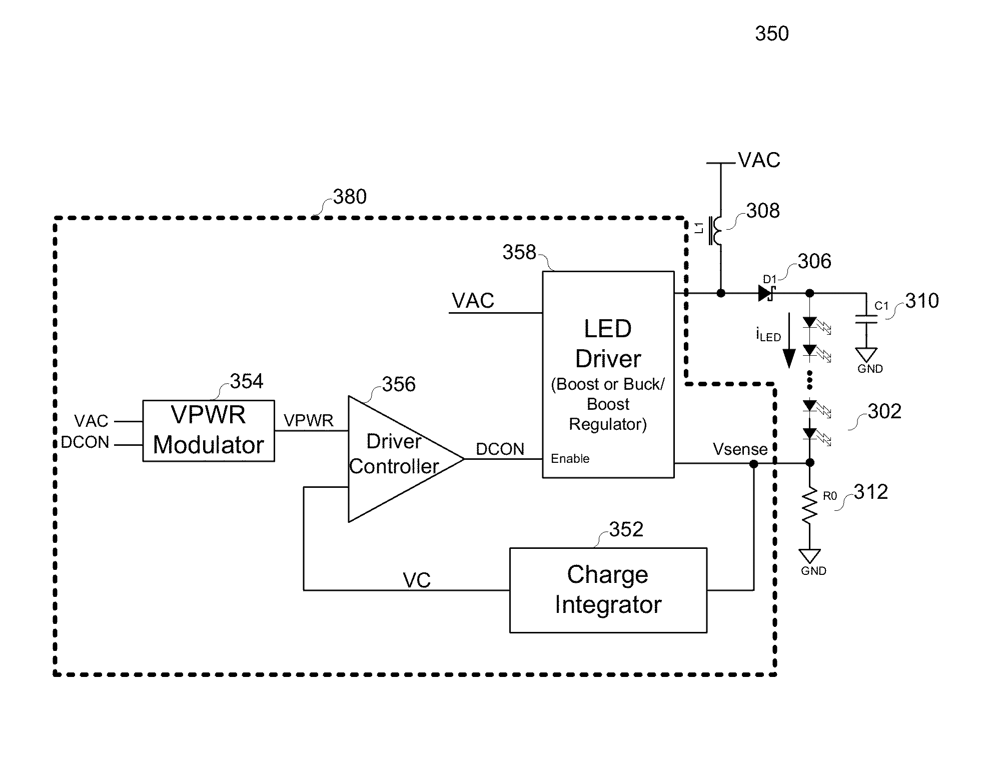
[0024]Various embodiments of the present invention relates to a LED illumination system, and more particularly, to systems, devices and methods of employing a LED driver control loop to adjust the brightness of the LED light smoothly and suppress flickering / blinking are suppressed. It will be apparent, however, to one skilled in the art that the invention can be practiced without these details. One skilled in the art will recognize that embodiments of the present invention, described below, may be performed in a variety of ways and using a variety of means. Those skilled in the art will also recognize additional modifications, applications, and embodiments are within the scope thereof, as are additional fields in which the invention may provide utility. Accordingly, the embodiments described below are illustrative of specific embodiments of the invention and are meant to avoid obscuring the invention.

[0025]Reference in the specification to “one embodiment” or “an embodiment” means t...


PUM


Abstract

Various embodiments of the present invention relate to a LED illumination system, and more particularly, to systems, devices and methods of employing a LED driver control loop to adjust the brightness of the LED light smoothly and suppress flickering/blinking. The LED driver control loop comprises a LED driver, a charge integrator, a VPWR modulator, and a driver controller. The charge integrator generates a voltage VC that is associated with a LED current iLED and illumination energy for the LED light. The VPWR modulator provides a clamping voltage VPWR such that the LED driver ceases to inject the LED current iLED as the voltage VC saturates at VPWR during each powering cycle. The clamping voltage VPWR is dynamically adjusted at the end of each powering cycle to gradually adjust the brightness and avoid flickering or blinking while still ensuring illumination efficiency.

Description

CROSS REFERENCE TO RELATED APPLICATION[0001]The application claims the benefit under 35 U.S.C. §119(e) of Provisional Application Ser. No. 61 / 490,978, entitled “A Self-Adjusted LED Illumination System”, filed on May 27, 2011, the subject matter of which is incorporated herein by reference.BACKGROUND[0002]A. Technical Field[0003]The present invention relates to a LED illumination system, and more particularly, to systems, devices and methods of employing a LED driver control loop for smooth brightness adjustment and flicker suppression.[0004]B. Background of the Invention[0005]Semiconductor-based solid-state lighting (SSL), until recently associated mainly with simple indicator lamps in electronics and toys, has become as bright and more efficient than other lighting technologies. In particular, the enormous technology improvements have been achieved on light emitting diodes (LEDs) over the past years. LEDs have been available for various wavelengths, and suitable for white illuminat...

Claims


Application Information

Patent Timeline
Patent Type & Authority Patents(United States)
IPC IPC(8): H05B37/02G05F1/00
CPCH05B37/02G05F1/00H05B45/10H05B45/375H05B45/3725H05B45/38H05B45/14
Inventor LOCASCIO, JAMES, JASON
Owner MAXIM INTEGRATED PROD INC
Why Eureka
Try Eureka