Method of resolving display delay

US20060055688A1Inactive Publication Date: 2006-03-16IND TECH RES INST
1 Cites 0 Cited by

Patent Information

Authority / Receiving Office
US · United States
Current Assignee / Owner
Publication Date
2006-03-16
Estimated Expiration
Not applicable · inactive patent

Smart Images

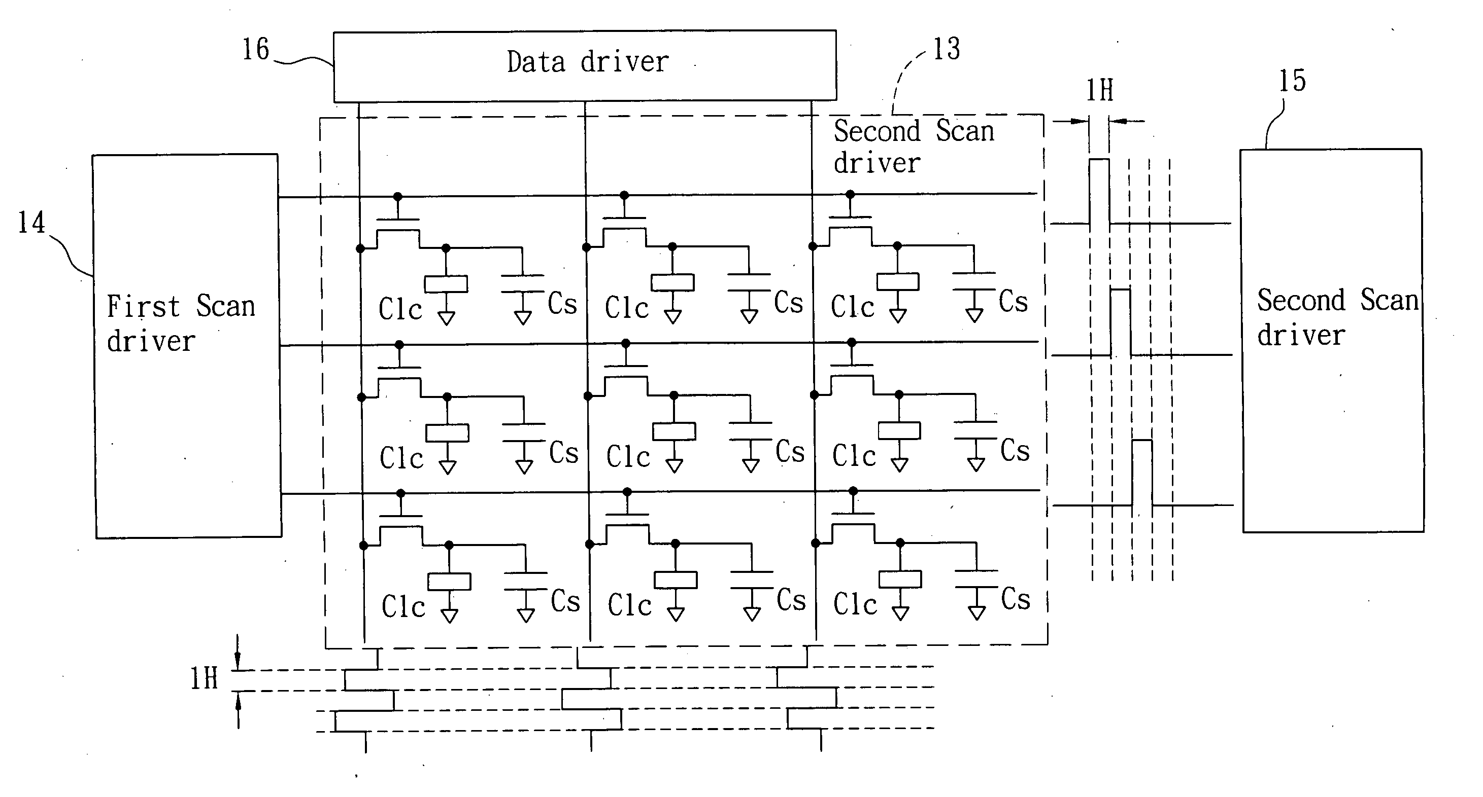
  • Figure 1
    Figure 1
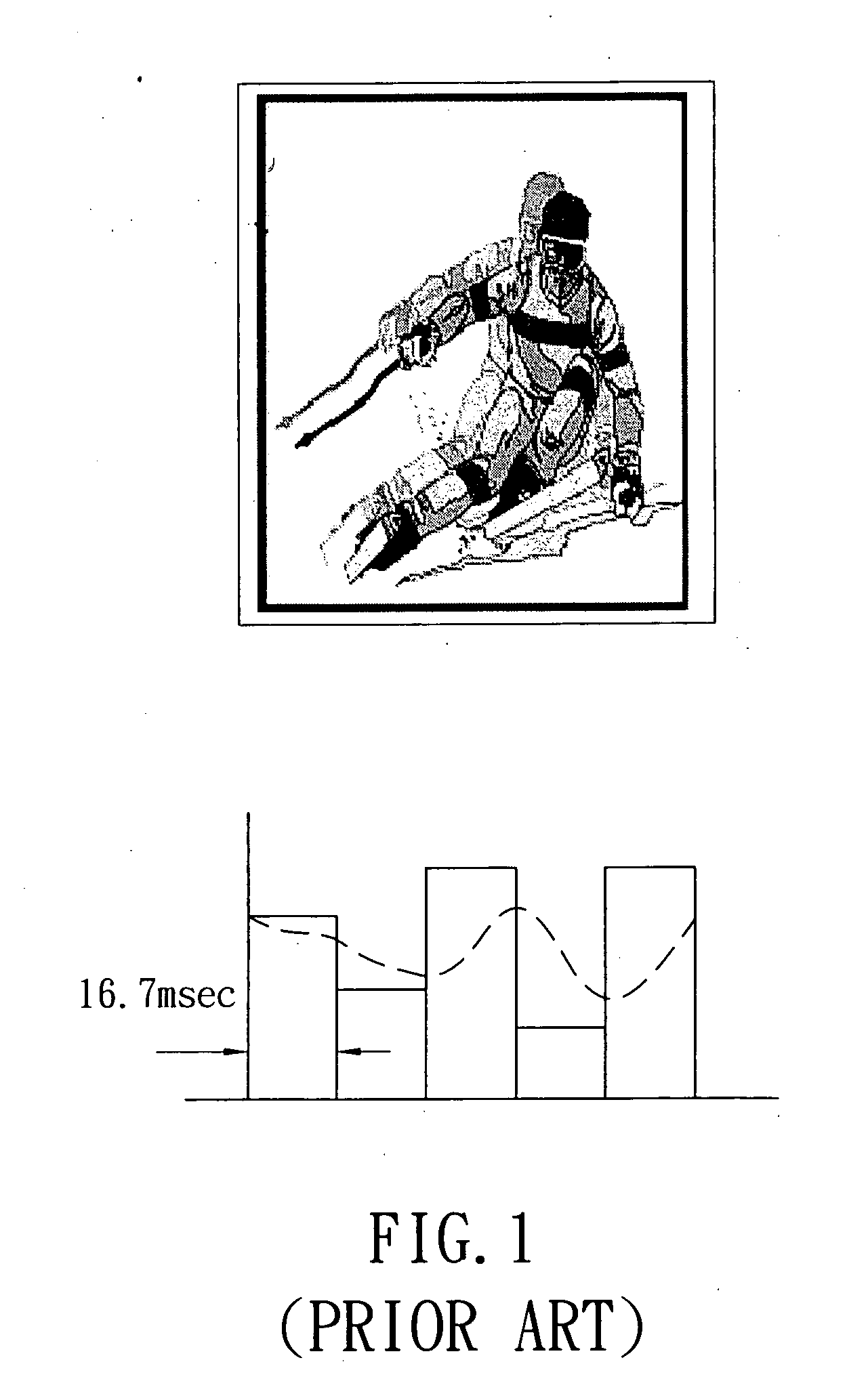
  • Figure 2
    Figure 2
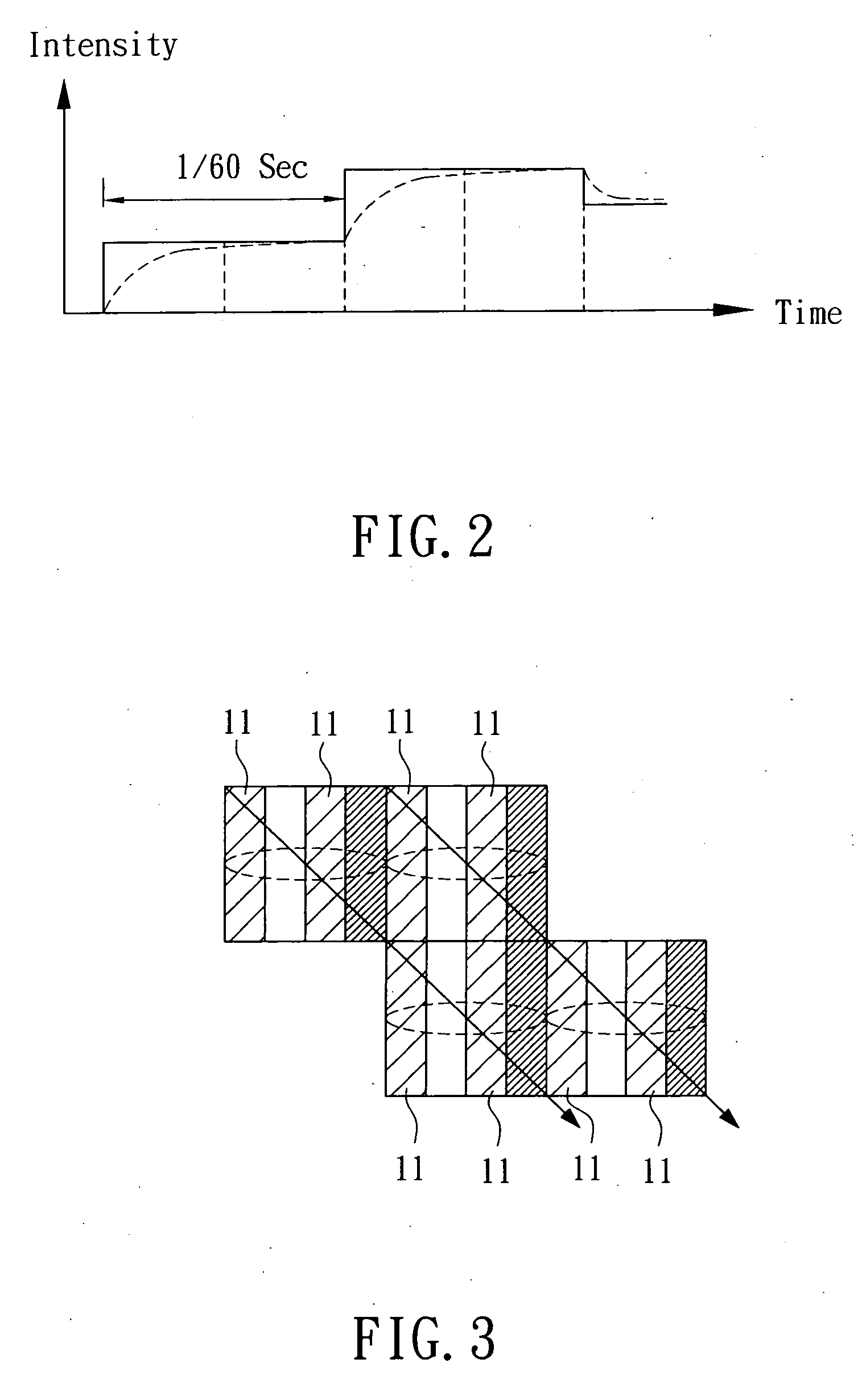
  • Figure 3
    Figure 3
Patent Text Reader

Abstract

A method of resolving display delay is disclosed. The method of resolving display delay comprises the steps of: dividing a period of turning on scan lines of an image is into at least two sections; and charging at least one section of the period while discharging the other sections of the period for enabling the charging of scan lines (i.e. enabling pixel displaying) and the discharging of scan lines (i.e. erasing pixel displaying) are performed with a designated number of scan lines apart so as to achieve the purpose of preventing the liquid crystal display from generating display delay and image-sticking phenomena.
Need to check novelty before this filing date? Find Prior Art

Description

FIELD OF THE INVENTION

[0001] The present invention relates to a method of resolving display delay, and more practically, to a method of providing continuous and uninterrupted images during digital image scan for increasing image quality. BACKGROUND OF THE INVENTION

[0002] The appearance and subsequent development of electronic products started only a few decades ago; however, the progressing speed of this industry has surpassed many others. This is especially so in the development of computer related periphery products and video-audio products. New products are ever emerging due to the needs of the working people and recreation needs of the general population. Much progress has been made in these areas; new products are ever emerging. Take the display product for instance; the conventionally used display is constituted of a Cathode Ray Tube (CRT), which usually has the following drawbacks:

[0003] 1. Since the conventional display is not equipped with flat screen, it is often suffer...

Examples

Embodiment Construction

[0019] For your esteemed members of reviewing committee to further understand and recognize the fulfilled functions and structural characteristics of the invention, several preferable embodiments cooperating with detailed description are presented as the follows.

[0020] Referring to FIG. 2, which is a waveform of hold-type displaying for LCDs according to the present invention. As seen in FIG. 2, the profile is a period curve of a scan line without intermittent displayed light. Referring to FIG. 3, which is a schematic illustration showing a mechanism of motion for LCDs according to the present invention. As seen in FIG. 3, it is the image displayed corresponding to the screen line period of the FIG. 2, wherein each field is composed of a plurality of single pixels 11 and the image is formed by a continue scanning that the image is formed by first scanning a screen horizontally and successively in a single direction, for example, the scanning is performed successively from the topmo...