Video synchronization device and method
A video synchronization and image synchronization technology, which is applied in the direction of TV, color TV, color TV parts, etc., can solve the problems of poor fluency and delay cost, and achieve the goal of avoiding display delay, reducing cost and saving storage components Effect
- Summary
- Abstract
- Description
- Claims
- Application Information
AI Technical Summary
Problems solved by technology
Method used
Image
Examples
Embodiment 1
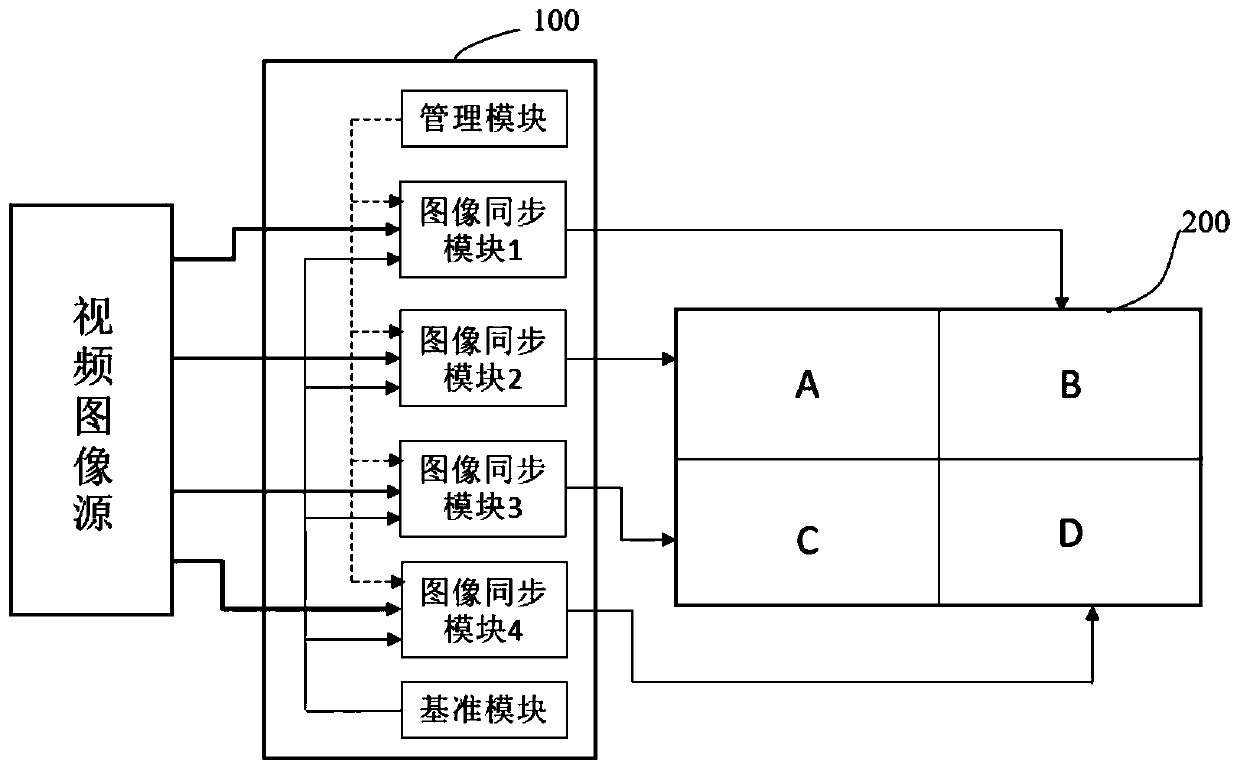
[0082] Such as figure 1 As shown, the splicing screen 200 is a 2×2 splicing screen composed of display screens A, B, C, and D. The video image of the video image source is output to the video synchronization device 100 of the present invention, and after being processed by the video synchronization device 100, it is output to the display screens A, B, C, and D respectively, and the display screens A, B, C, and D are spliced to form a A complete picture of the splicing screen 200. Wherein, the video synchronization device 1 includes: an image synchronization module and a reference module. Exemplary, figure 1 There are four image synchronization modules in the video synchronization device 1, which are respectively image synchronization modules 1-4.
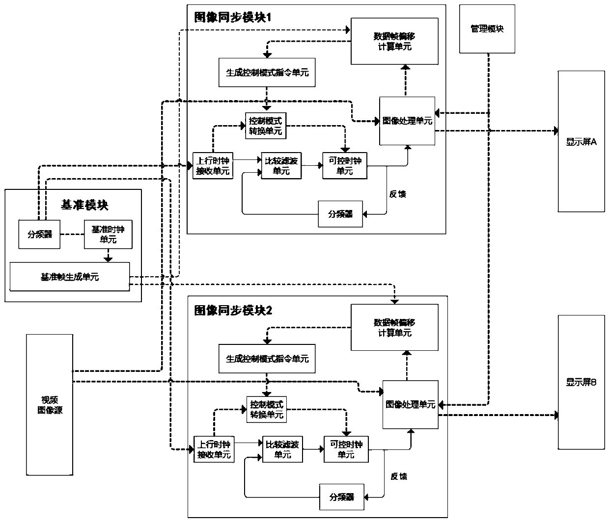
[0083] Such as figure 2 as shown, figure 2 The connection relationship between the internal components of the image synchronization module and the reference module is shown in detail. Since the internal structure of each im...
Embodiment 2
[0105] Corresponding to the video synchronization device in Embodiment 1, the present invention also proposes a video synchronization method, which is similar to Embodiment 2, and the overall flow chart of the method is as follows Figure 5 shown.
[0106] A video synchronization method, the method is used in a video synchronization device, the video synchronization device includes: a controllable clock unit, an image processing unit; the controllable clock unit can generate multiple frequencies within a preset range The clock signal of; Described method comprises the following steps:
[0107] S1. Determine the reference frame;
[0108] S2. Obtain the data frame sent by the image processing unit, and calculate the data frame offset value between the obtained data frame and the reference frame;
[0109] S3. Adjust the frequency of the clock signal generated by the controllable clock unit according to the data frame offset value;
[0110] S4. The image processing unit generat...
PUM
 Abstract
Description
Claims
Application Information
 - R&D
- Intellectual Property
- Life Sciences
- Materials
- Tech Scout
- Unparalleled Data Quality
- Higher Quality Content
- 60% Fewer Hallucinations
Browse by: Latest US Patents, China's latest patents, Technical Efficacy Thesaurus, Application Domain, Technology Topic, Popular Technical Reports.
© 2025 PatSnap. All rights reserved.Legal|Privacy policy|Modern Slavery Act Transparency Statement|Sitemap|About US| Contact US: help@patsnap.com


