
Indoor ground water supply pipeline concealed laying and groove pressing tool and use method thereof

A technology for water supply pipes and indoor floors, which is applied in the field preparation of formwork/formwork/work frame, building components, construction, etc., to achieve the effects of low production cost, convenient production, and good visual effect

Inactive Publication Date: 2018-12-28
MCC5 GROUP CORP SHANGHAI
View PDF5 Cites 0 Cited by
  • Summary
  • Abstract
  • Description
  • Claims
  • Application Information

AI Technical Summary

Problems solved by technology

[0003] Therefore, there are above-mentioned inconveniences and problems in the known indoor ground water supply pipeline concealed pressure groove mode.

Method used


Image

  • Indoor ground water supply pipeline concealed laying and groove pressing tool and use method thereof
  • Indoor ground water supply pipeline concealed laying and groove pressing tool and use method thereof

Examples


Embodiment 1

[0034] The hidden pressure groove tool for indoor ground water supply pipeline of the present invention comprises two steel pipes and four supporting plates.

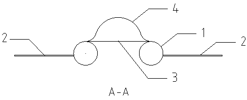
[0035] see now figure 1 and figure 2 , figure 1 It is a structural schematic diagram of a grooving tool according to an embodiment of the present invention, figure 2 for figure 1 Sectional view of A-A in Fig. As shown in the figure, the two steel pipes 1 each have a length of 2m, are arranged in parallel, and have a mutual spacing of 50mm; A handle 4 is solidly welded on the surface of the steel plate 3 at both ends; the steel pipe 1 is a DN50 steel pipe. The steel plate 3 is a 50*150*2mm steel plate. The handle 4 is an arc-shaped handle made of round steel with a diameter of 8 mm. Described handle can also be made into Π shape handle.

[0036] The four supporting plates 2 are 100*200*2mm steel plates, which are fixedly welded on the outer sides of the two parallel steel pipes where the handle is located in a ...

Embodiment 2

[0038] A method for using a concealed pressure groove tool for indoor ground water supply pipelines. The diameter of the steel pipe 1 needs to be determined according to the designed pressure groove width, and the diameter of the steel pipe 1 is determined according to the designed pressure groove depth, and the bottom end of the steel pipe 1 is determined. The distance processing to the lower surface of supporting plate 2 is made as the embossing tool of embodiment 1, comprises the following steps during use:

[0039] a. Before concrete pouring, use thin iron wire to locate the position where the water supply pipe needs to be pressed.

[0040] b. After the initial setting of the concrete has a certain strength, after 4-6 hours, grasp the handle 4 of the grooving tool with your hands to make the grooving, and use the gravity of the steel pipe 1 to press the groove from one end of the building to the other end, so that the supporting plate 2 The lower surface of the floor coinc...


PUM


Abstract

An indoor ground water supply pipeline concealed laying and groove pressing tool comprises two steel pipes and four supporting plates, and is characterized in that the length of each of the two steelpipes (1) is larger than or equal to 2 m, the steel pipes are arranged in parallel, and the distance between the steel pipes is 50 mm; three steel plates (3) are arranged on the upper surfaces of thetwo steel pipes so as to fixedly connect the two steel pipes, and handles (4) are fixedly welded to the surfaces of the steel plates (3) at the two ends of the two steel pipes; the four supporting plates (2) are fixedly and correspondingly welded to the outer sides of the two parallel steel pipes in pairs, and the handles are located on the two parallel steel pipes. The indoor ground water supplypipeline concealed laying and groove pressing tool and a use method thereof have the advantages that the groove pressing tool is simple in structure and convenient to manufacture, it is ensured that the widths and depths of pressed grooves are consistent, the use is convenient, the production cost is low, the groove pressing position is accurate, and groove pressing is good in appearance effect.

Description

technical field [0001] The invention relates to an auxiliary tool for floor concrete construction, in particular to an indoor ground water supply pipe concealed pressing groove tool. Background technique [0002] The laying of indoor water supply pipelines is divided into two methods: exposed laying and concealed laying. The exposed laying is generally used in places that do not have special requirements for hygiene and aesthetics, while the concealed laying method is generally designed for places that have high requirements for hygiene and aesthetics. Among them, during the construction process of the concealed laying method, it is necessary to groove the floor before the floor construction or to press the groove after the floor concrete is poured and before the final setting, but the width and depth of the groove or the pressure groove are quite difficult to control. [0003] Therefore there are above-mentioned inconveniences and problems in the known indoor ground water s...

Claims


Application Information

Patent Timeline
Patent Type & Authority Applications(China)
IPC IPC(8): E04G15/06
CPCE04G15/063
Inventor 刘栋
Owner MCC5 GROUP CORP SHANGHAI
Learn More