
Siderail for hospital bed

Active Publication Date: 2006-03-23
KREG MEDICAL
View PDF99 Cites 102 Cited by
  • Summary
  • Abstract
  • Description
  • Claims
  • Application Information

AI Technical Summary

Benefits of technology

[0013] According to another embodiment, the bed also has a sensor that senses when the siderail assembly is in the disengaged state. The sensor provides a signal to a controller to prevent the third deck section from moving to the substantially vertical position when the siderail assembly is in the disengaged state.
[0017] According to another embodiment, the siderail has a sling connected thereto to assist a patient to exit the chair bed. Additionally, a leg harness may be provided adjacent the third deck section to retain the patient's legs.

Problems solved by technology

While such siderails according to the prior art provide a number of advantageous features, they nevertheless have certain limitations.

Method used


Image

  • Siderail for hospital bed
  • Siderail for hospital bed
  • Siderail for hospital bed

Examples


Embodiment Construction

[0071] While this invention is susceptible of embodiments in many different forms, there is shown in the drawings and will herein be described in detail preferred embodiments of the invention with the understanding that the present disclosure is to be considered as an exemplification of the principles of the invention and is not intended to limit the broad aspect of the invention to the embodiments illustrated.

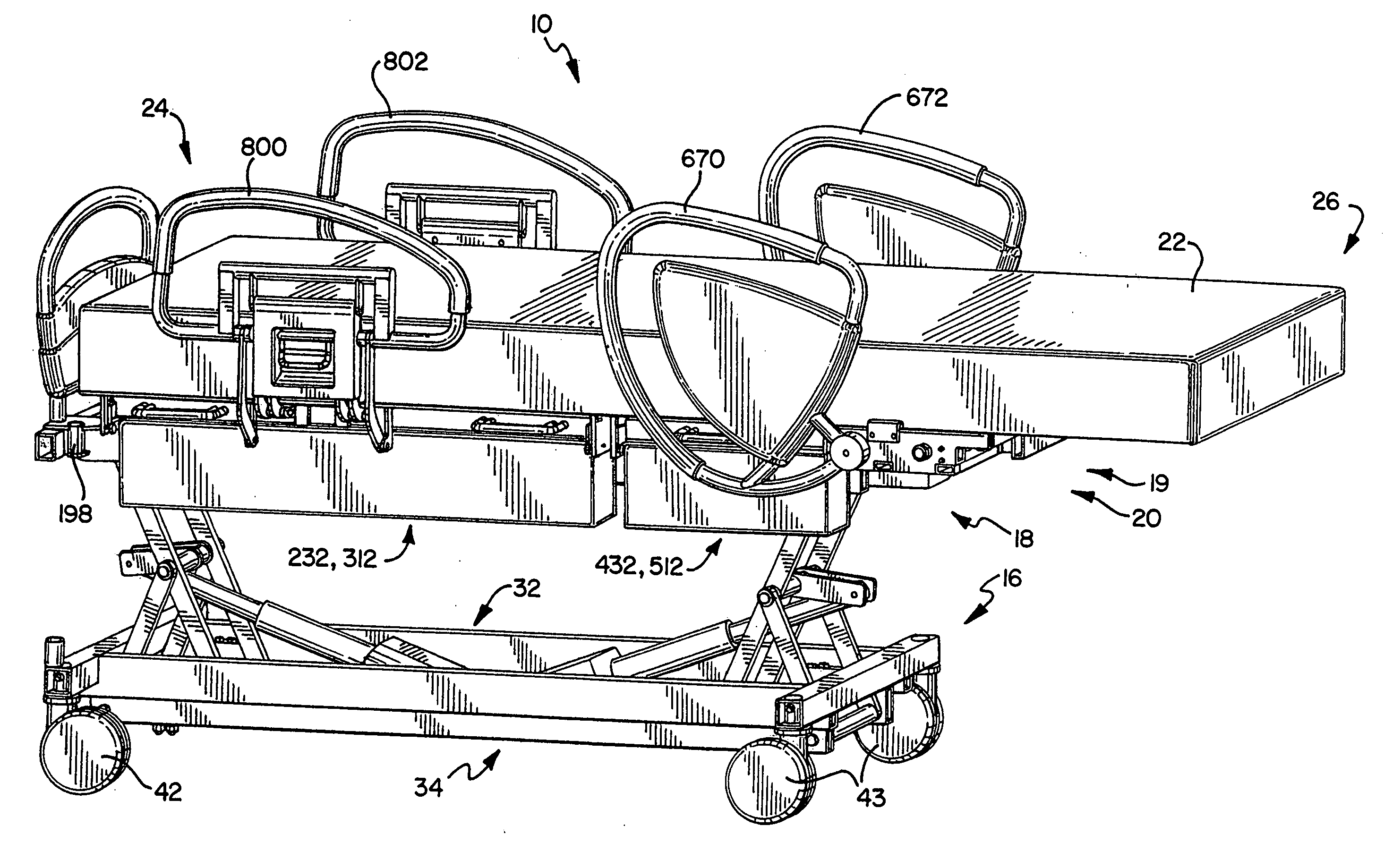
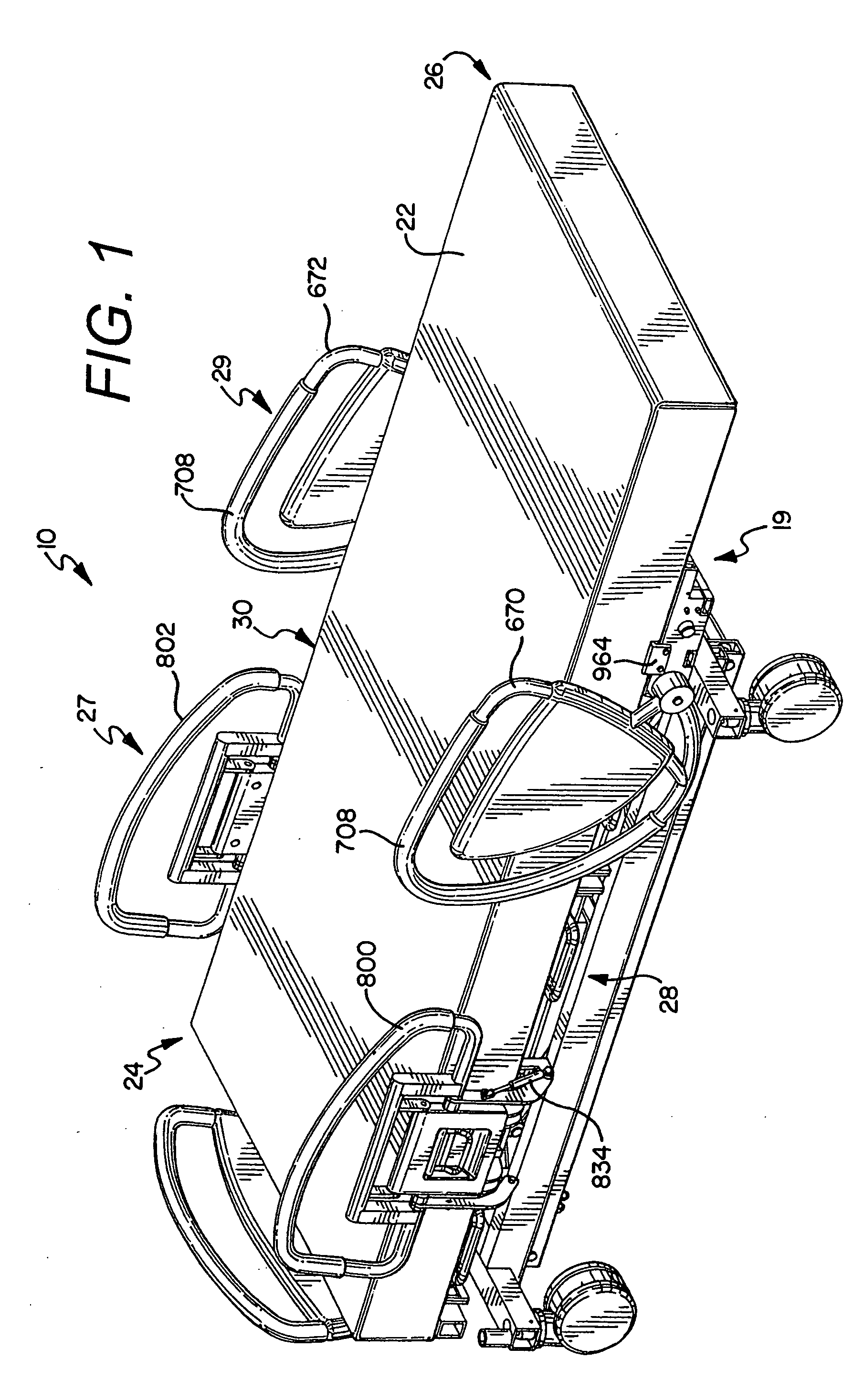
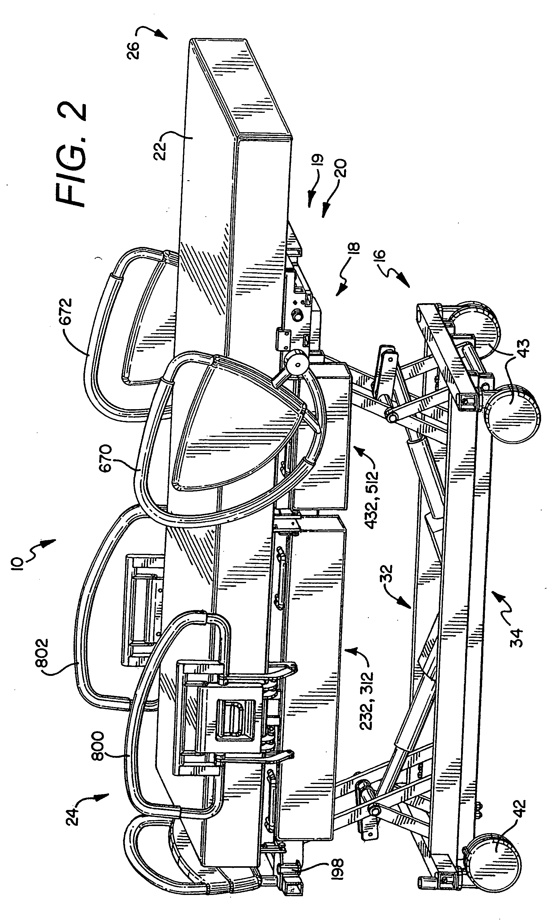
[0072] Referring now to the Figures, there are shown various embodiments of a hospital bed 10. The term “bed” herein is used to denote any embodiment of a support for a patient As such, in different embodiments the “bed” is provided as a chair bed 10 as shown for example in FIG. 34, and an expandable width bed 10 as shown for example in FIGS. 2, 34 and 38, a stretcher or gurney (not shown), etc. In the chair bed configuration the bed is manipulated to achieve both a conventional bed position having a substantially horizontal patient support or sleeping surface upon which a us...


PUM


Abstract

A siderail assembly for a hospital bed is provided. In one embodiment the bed is a chair bed having a first deck section, a second deck section and a third deck section. A pair of siderails are operably connected to the third deck section of the bed. In another embodiment, the siderail coupled to the third deck section remains stationary relative to the third deck section during movement of the third deck section between the generally horizontal and the substantially vertical position. The siderail is configured to be gripped by a patient while the patient is entering and exiting the chair bed.

Description

CROSS-REFERENCE TO RELATED APPLICATIONS [0001] This application is a continuation-in-part of U.S. Provisional Patent Application Ser. No. 60 / 609,390, filed on Sep. 13, 2004, which is expressly incorporated herein by reference.FEDERALLY SPONSORED RESEARCH OR DEVELOPMENT [0002] Not Applicable. TECHNICAL FIELD [0003] The present invention relates generally to a siderail for a bed, and more specifically to a siderail connected to a foot deck section of a chair bed. BACKGROUND OF THE INVENTION [0004] Siderails for hospital beds are well known in the art. While such siderails according to the prior art provide a number of advantageous features, they nevertheless have certain limitations. The present invention seeks to overcome certain of these limitations and other drawbacks of the prior art, and to provide new features not heretofore available. A full discussion of the features and advantages of the present invention is deferred to the following detailed description, which proceeds with ...

Claims


Application Information

Patent Timeline
IPC IPC(8): A47C21/08A61G7/00
CPCA61G7/005A61G7/012A61G7/015A61G7/05A61G2007/0514A61G7/053A61G7/16A61G2007/0509A61G7/0507A61G7/0509A61G7/0514
Inventor POULOS, CRAIGHARRIS, PATRICKSOLTANI, SOHRAB
Owner KREG MEDICAL
Learn More