Cheek-mounted patient interface

Inactive Publication Date: 2006-03-23
RIC INVESTMENTS LLC
View PDF12 Cites 330 Cited by
  • Summary
  • Abstract
  • Description
  • Claims
  • Application Information

AI Technical Summary

Benefits of technology

[0017] The patient interface of the present invention also includes two discrete cheek interfaces attached to the support body. Each of the cheek interfaces are designed to positively engage a corresponding cheek of the user so that it is securely affixed. As discrete components, each cheek interface may be moved independently relative to one another so that the patient interface may be easily customized for use with different users. To hold the patient interface in place about the patient's nose, the present invention also includes a headgear assembly which pulls the mask securely against the face of the user. The compressive forces exerted by the headgear assembly are distributed between the patient interface cushion and the discrete cheek interfaces thus providing three separate points of contact with the user's face.
[0018] These

Problems solved by technology

Sleep apnea syndrome results in episodic upper airway obstruction during sleep.
As a consequence, there is repeated interruption of sleep in the patient.
However, this solution oftentimes results in discomfort to the user due to relatively high strapping forces needed to ensure a secure seal against the patient and less than satisfactory patient compliance.
However, the effectiveness of the mask may be compromised if it is too loose.
As the mask is tightened, the force exerted by the headgear is concentrated about the patient's nose and may be deemed uncomfortable by some patients.
Moreover, th

Method used


Image

  • Cheek-mounted patient interface
  • Cheek-mounted patient interface
  • Cheek-mounted patient interface

Examples


Embodiment Construction

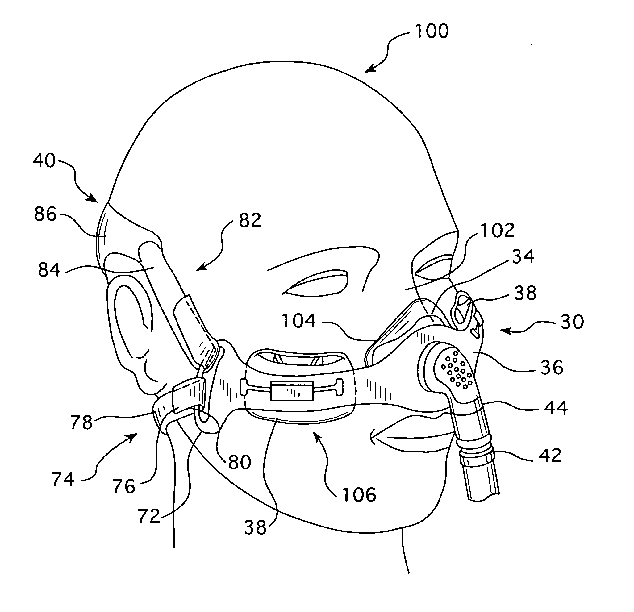
[0025]FIG. 1 schematically illustrates an exemplary embodiment of a patient interface 30 according to the principles of the present invention. As shown in FIG. 1, patient interface 30 is configured to be securely mated to a user 100 in order to deliver gas at a positive pressure for consumption by the user. Patient Interface 30 includes a user interface cushion 34 supported by a support body 36 and a two cheek interfaces 38. The patient interface is held in place by a headgear assembly 40. Gas is delivered to mask assembly 30 via a conduit 42 connected between a gas compressor, not shown, and a coupling 44 attached to the support body 36. Coupling 44 may have a variety of configurations. However, in an exemplary embodiment of the present invention, as shown in FIG. 1, coupling 44 has an L-shaped configuration.

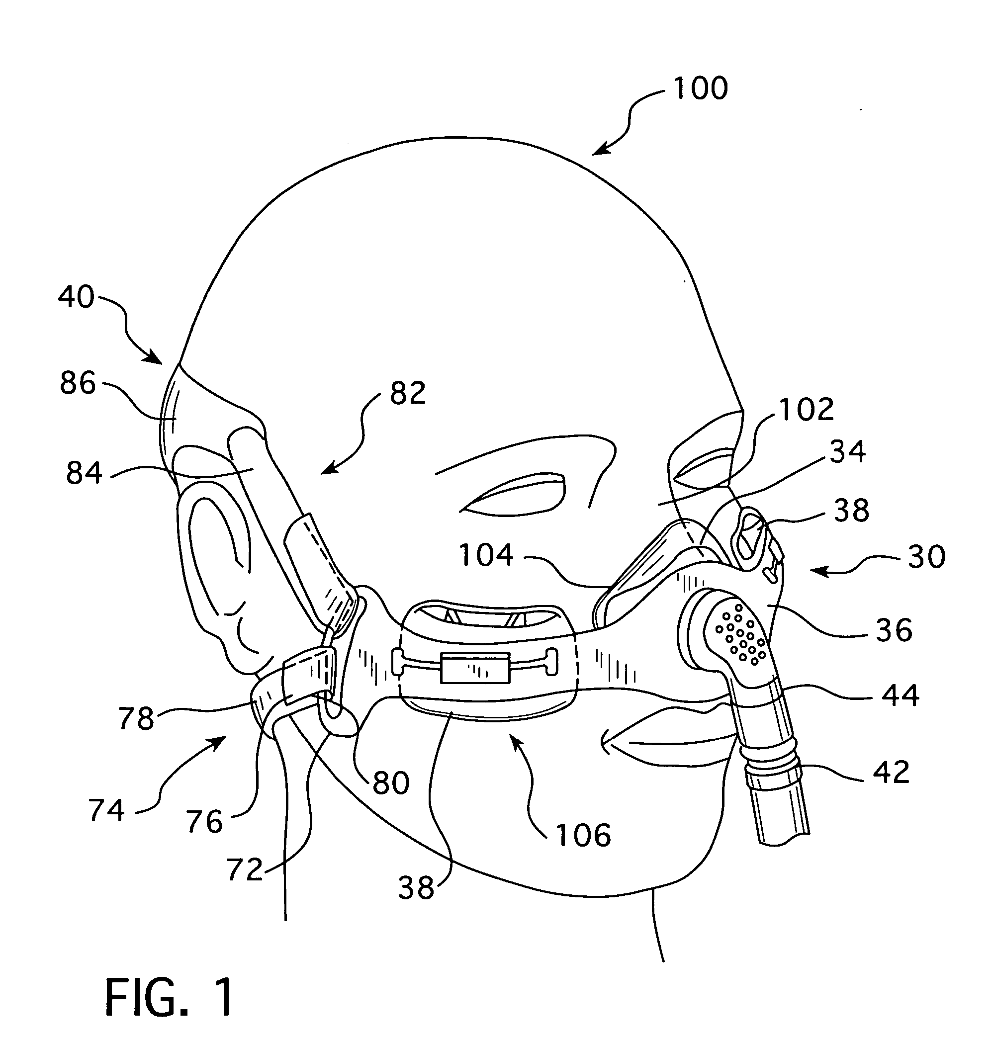
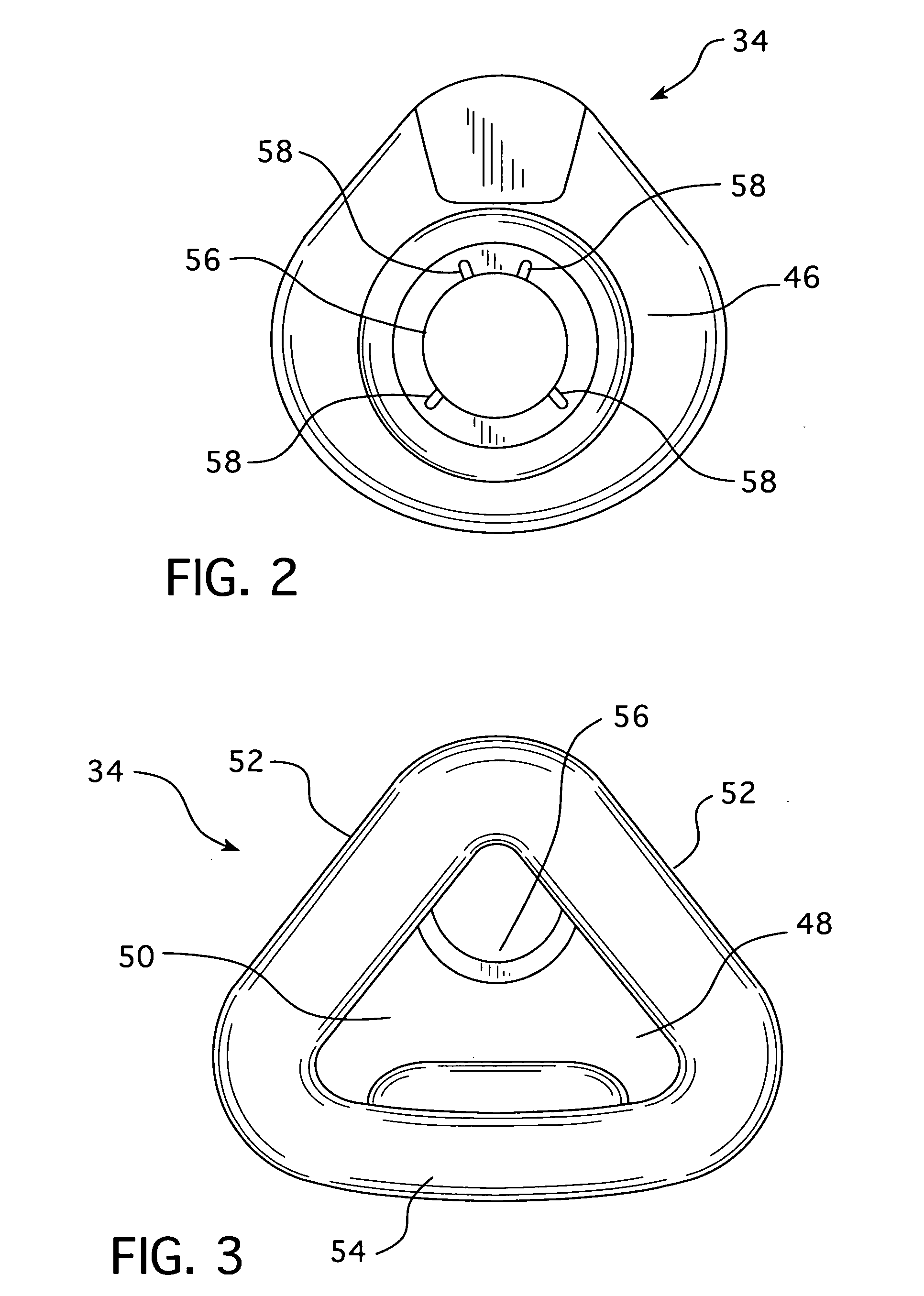
[0026] Turning to FIGS. 2 and 3, the present invention utilizes a contemporary interface cushion. An example of such a cushion is described in detail in U.S. Pat. No. 6,651,66...


PUM


Abstract

A patient interface that includes a support body having a cushion and cheek interfaces. Collectively, the cushion and cheek interfaces operate to distribute compressive forces exerted on the user's face. The support body of the patient interface is constructed from a flexible material to impart additional adjustability to the cheek interfaces. The support body also has arcuate eyelets designed to provide a hinge between the headgear assembly and the support body.

Description

CROSS-REFERENCE TO RELATED APPLICATIONS [0001] Under the provisions of 35 U.S.C. § 119(e), this application claims the benefit of U.S. Provisional Application Ser. No. 60 / 611,867, filed Sep. 21, 2004.BACKGROUND OF THE INVENTION [0002] 1. Field of the Invention [0003] The present invention pertains to a respiratory patient interface used to deliver gas to a user and a method for using the same. In particular, the present invention is related to a flexible, cheek mounted patient interface that includes self-adjustment features to enhance the patient's comfort. [0004] 2. Description of the Related Art [0005] A variety of delivery systems are known that provide gas at positive pressure for consumption by the patient. The uses and applications of such systems vary. Some such systems have been developed for the treatment of sleep apnea and other sleep related disorders. [0006] Sleep apnea syndrome results in episodic upper airway obstruction during sleep. As a consequence, there is repeat...

Claims


Application Information

Patent Timeline
IPC IPC(8): A62B7/10A62B18/08
CPCA61M16/0616A61M16/0683
Inventor HO, PETER CHI FAIBUSCH, LANCEMATULA, JEROME JR.
Owner RIC INVESTMENTS LLC
Why Eureka
Try Eureka