Electronically controlled valve for a materials handling vehicle

Active Publication Date: 2006-03-23
CROWN EQUIP CORP
View PDF60 Cites 47 Cited by
  • Summary
  • Abstract
  • Description
  • Claims
  • Application Information

AI Technical Summary

Benefits of technology

[0013] In accordance with a second aspect of the present invention, a materials handling vehicle is provided comprising: a base; a carriage assembly movable relative to the base; at least one cylinder coupled to the base to effect movement of the carriage assembly relative to the base; and a hydraulic system to supply a pressurized fluid to the cylinder. The hydraulic system includes an electronically controlled valve coupled to the cylinder. Further provided is control structure to control the ope

Problems solved by technology

Hence, such fuses will not permit controlled downward movement of a carriage assembly at a speed in excess of about 120 feet/minute.
It is noted that when a velocity fuse closes, it closes very quickly resulting in a hydraulic fluid pressure spike occurring w

Method used


Image

  • Electronically controlled valve for a materials handling vehicle
  • Electronically controlled valve for a materials handling vehicle
  • Electronically controlled valve for a materials handling vehicle

Examples


Embodiment Construction

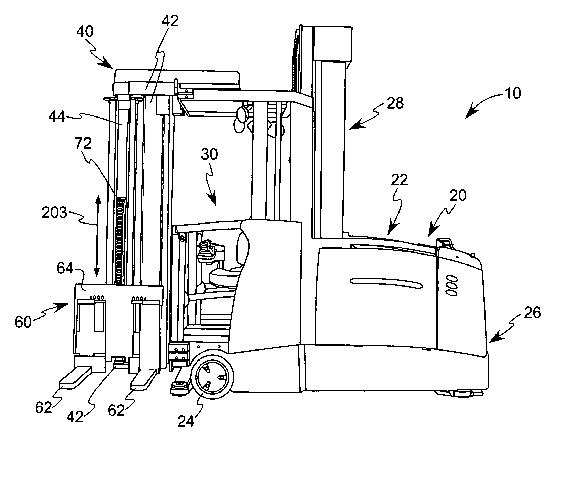
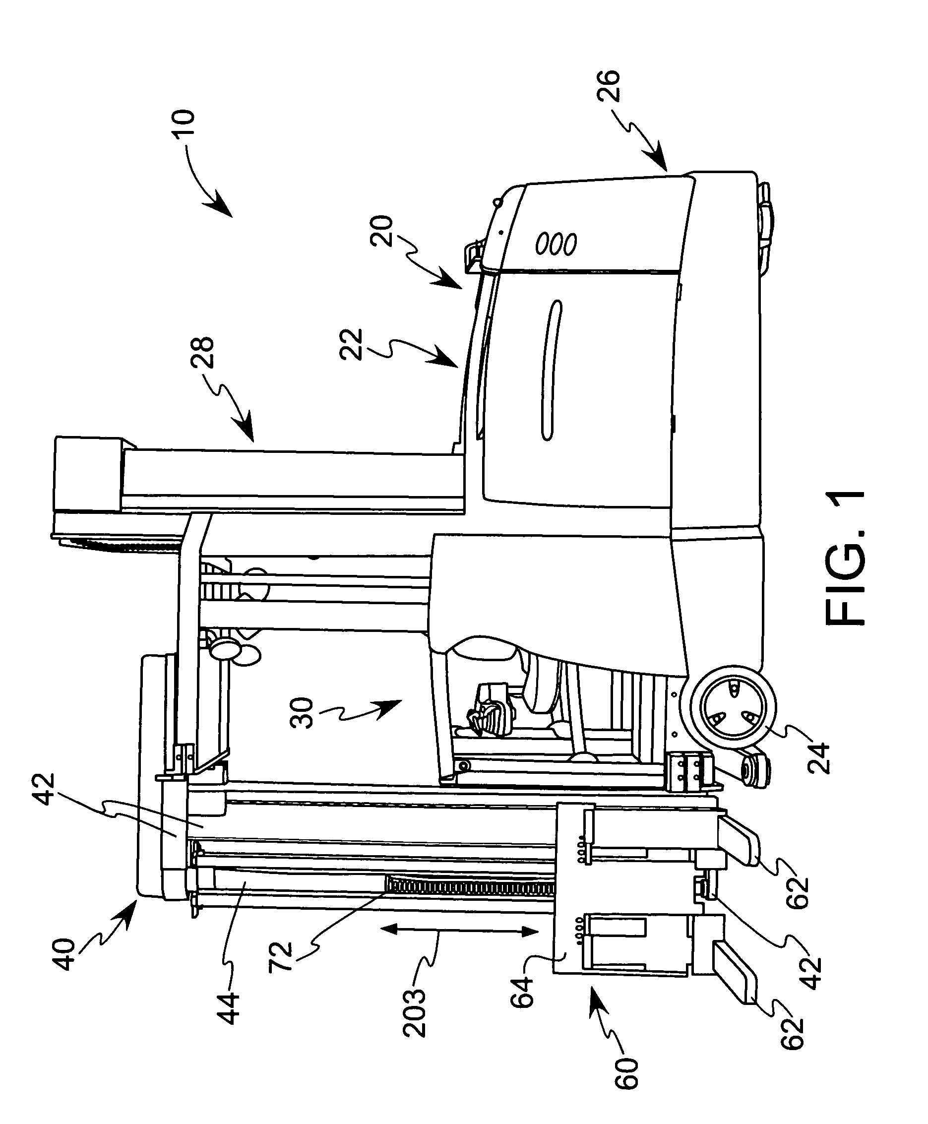
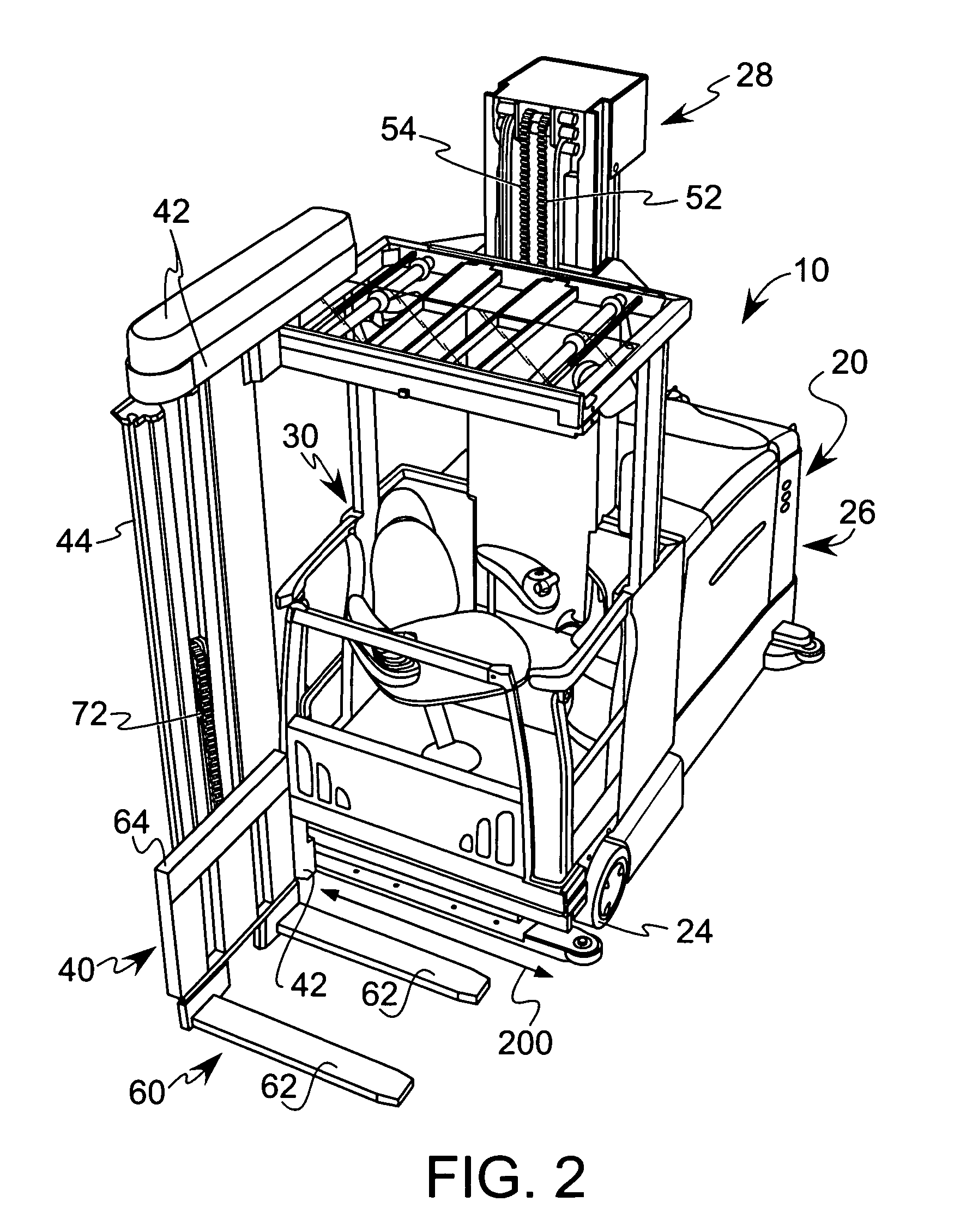
[0029] Referring now to the drawings, and particularly to FIGS. 1-4 and 6, which illustrate a materials handling vehicle 10 constructed in accordance with the present invention. In the illustrated embodiment, the vehicle 10 comprises a turret stockpicker. The vehicle 10 includes a power unit 20, a platform assembly 30 and a load handling assembly 40. The power unit 20 includes a power source, such as a battery unit 22, a pair of load wheels 24, see FIG. 6, positioned under the platform assembly 30, a steered wheel 25, see FIG. 4, positioned under the rear 26 of the power unit 20, and a mast assembly 28 on which the platform assembly 30 moves vertically. The mast assembly 28 comprises a first mast 28a fixedly coupled to the power unit 20, and a second mast 28b movable coupled to the first mast 28a, see FIGS. 4 and 6.

[0030] A mast piston / cylinder unit 50 is provided in the first mast 28a for effecting movement of the second mast 28b and the platform assembly 30 relative to the first ...


PUM


Abstract

A materials handling vehicle is provided comprising: a base; a carriage assembly movable relative to the base; at least one cylinder coupled to the base to effect movement of the carriage assembly relative to the base; and a hydraulic system to supply a pressurized fluid to the cylinder. The hydraulic system includes an electronically controlled valve coupled to the cylinder. The vehicle further comprises control structure to control the operation of the valve such that the valve is closed in the event of an unintended descent of a carriage assembly in excess of a commanded speed.

Description

TECHNICAL FIELD [0001] The present invention relates to an electronically controlled valve coupled to a lift cylinder which, in turn, is coupled to a carriage assembly, wherein the valve is controlled so as to close in the event of an unintended descent of the carriage assembly. BACKGROUND OF THE INVENTION [0002] A materials handling vehicle is known in the prior art comprising a base unit including a power source and a mast assembly. A fork carriage assembly is coupled to the mast assembly for vertical movement relative to the power source with at least one cylinder effecting vertical movement of the carriage assembly. A hydraulic system is coupled to the cylinder for supplying a pressurized fluid to the cylinder, and includes an ON / OFF blocking valve positioned in a manifold for preventing the carriage assembly from drifting downwardly when raised via the cylinder to a desired vertical position relative to the power source. A metering valve, also positioned in the manifold, define...

Claims


Application Information

Patent Timeline
IPC IPC(8): B60K17/00
CPCA47L11/282B66F9/22B66F17/003
Inventor DAMMEYER, KARL L.JONES, WILLIAM C. JR.
Owner CROWN EQUIP CORP
Why Eureka
Try Eureka