Image pickup device

a pickup device and image technology, applied in the field of image pickup devices, can solve the problems of two image signals not being synchronized with each other, and the pick-up image cannot be displayed simultaneously on the image display

Inactive Publication Date: 2006-03-23
SONY CORP
View PDF10 Cites 25 Cited by
  • Summary
  • Abstract
  • Description
  • Claims
  • Application Information

AI Technical Summary

Problems solved by technology

However, if a frame rate of an image signal generated by an image pick-up device with a variable frame-rate and that of an image signal supplied from a reproduction device are different from each other, these two image signals cannot be synchronized with each other, so that the reproduced image and the picked-up image cannot be displayed simultaneously on the image display.

Method used


Image

  • Image pickup device
  • Image pickup device
  • Image pickup device

Examples


Embodiment Construction

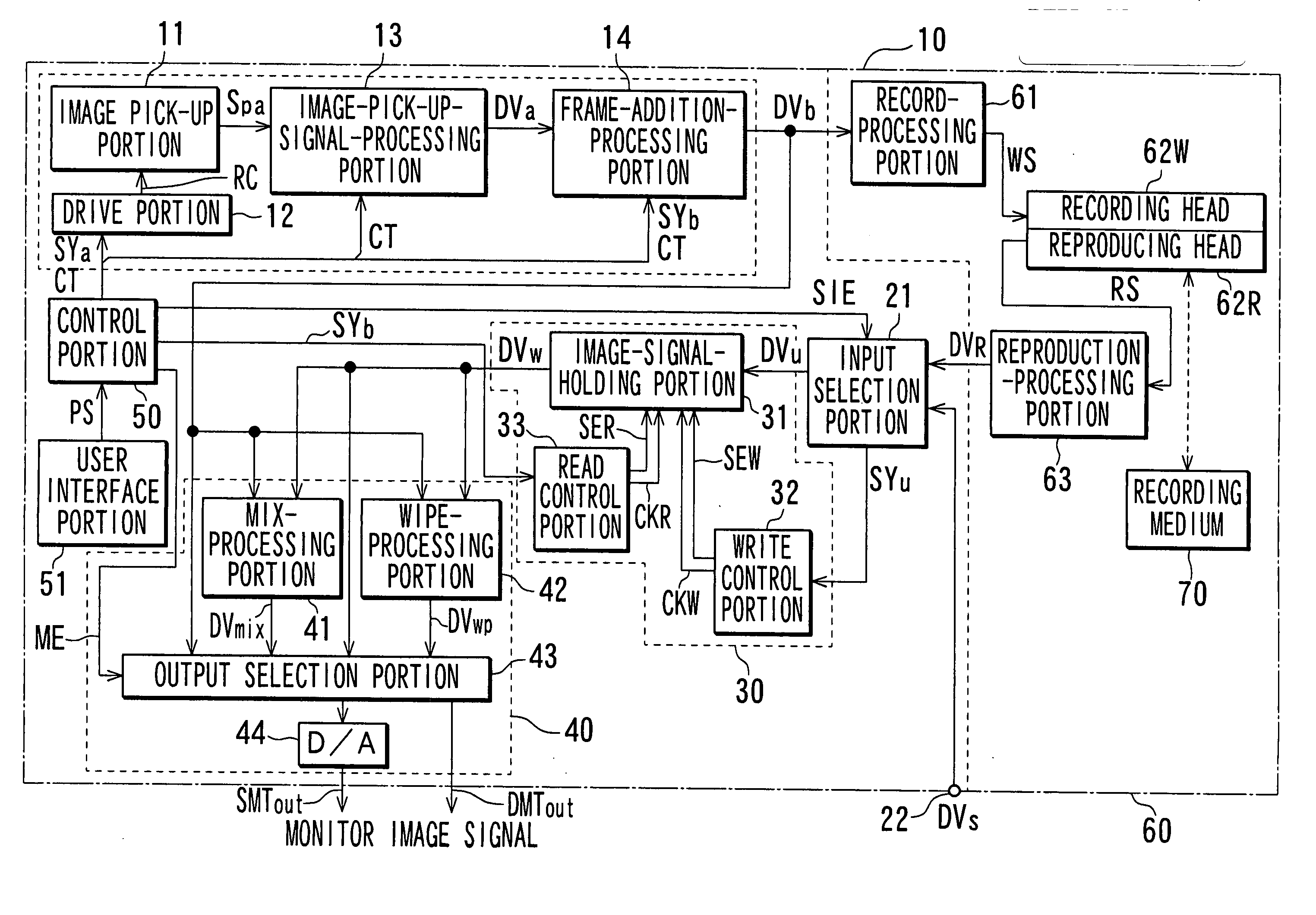
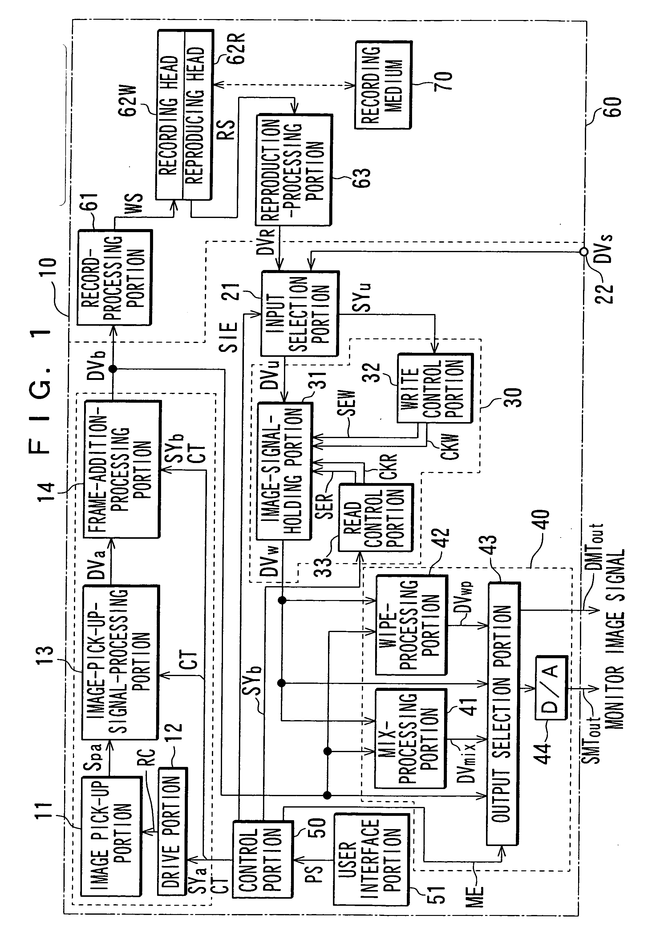
[0030] The following will describe one embodiment of the present invention with reference to drawings. FIG. 1 shows a configuration of an image pick-up device. An image of a subject based on light entering through an image pick-up lens (not shown) is formed on an image pick-up surface of an image pick-up element (not shown) that constitutes an image pick-up portion 11 in an image signal generation portion 10. The image pick-up element generates image pick-up charge for the subject image through photoelectric transfer and reads this image pick-up charge based on a drive-and-control signal RC supplied from a drive portion 12 to convert it into a voltage signal. Furthermore, it supplies this voltage signal as a picked-up image signal Spa to an image-pick-up-signal-processing portion 13.

[0031] The drive portion 12 generates the drive-and-control signal RC based on a control signal CT and a synchronization signal SYa that are supplied from a control portion 50, which will be described l...


PUM


Abstract

An image signal generation portion 10 generates an image signal DVb of a variable frame-rate picked-up image whose frame rate can be varied. A frame rate conversion portion 30 converts a frame rate of an image signal DVu supplied to it into a frame rate of the image signal DVb and synchronizes them to provide an image signal DVw. A monitor image signal generation portion 40 uses the image signals DVb and DVw to generate an image signal DVmix of an image in which an image based on the image signal DVb and an image based on the image signal DVw are mixed and output it as a monitor image signal DMTout or SMTout. Alternatively, it generates an image signal DVwp of an image in which a part of an image based on the image signal DVb is replaced by an image based on the image signal DVw and outputs it as the monitor image signal DMTout or SMTout. It is possible to simultaneously display a variable frame-rate picked-up image and an image having a different frame rate.

Description

TECHNICAL FIELD [0001] The present invention relates to an image pick-up device. More specifically, it relates to an operation of matching frame rate of a first image signal of a variable frame-rate picked-up image and that of a second image signal supplied from an outside with each other and using these first and second image signals having this matched frame rate to generate a monitor image signal. BACKGROUND ART [0002] In conventional filmmaking etc., to obtain special video effects, scenes have been shot in condition where a shooting speed of a film camera, that is, the number of frames per second has been varied. For example, if a scene is shot at a higher speed than an ordinary one and reproduced at the ordinary speed, images are reproduced slowly. Therefore, fast motion of, for example, a water droplet falling into the water can be observed easily and in detail. If a scene is shot at a lower speed than the ordinary one and reproduced at the ordinary speed, on the other hand, ...

Claims


Application Information

Patent Timeline
Patent Type & Authority Applications(United States)
IPC IPC(8): H04N5/228H04N5/225H04N5/232H04N5/262H04N5/265H04N5/272H04N5/77H04N5/775H04N5/93H04N7/01
CPCH04N5/23245H04N5/23293H04N5/775H04N5/272H04N5/772H04N5/265H04N23/667H04N23/63
Inventor KANEKO, KATSUMIKIHARA, TAKUSUDO, FUMIHIKO
Owner SONY CORP
Why Eureka
Try Eureka