
Configurable entertainment network

a technology of entertainment network and network, applied in the field of entertainment system, can solve the problems of requiring a relatively significant effort for changes to the system, and a rather involved task in adding or removing components from the system

Inactive Publication Date: 2006-03-23
AVAGO TECH WIRELESS IP SINGAPORE PTE
View PDF14 Cites 114 Cited by
  • Summary
  • Abstract
  • Description
  • Claims
  • Application Information

AI Technical Summary

Benefits of technology

"The present invention is a configurable entertainment network that can be easily set up and used. The network can be expanded and configured based on the needs of its users. The network can be sensed and activated when a user presses a button, and the network can automatically connect components to each other and allocate bandwidth for communication. The network can also be configured using a user interface, allowing for the addition of new components and the allocation of bandwidth for each connection. Overall, the invention provides a flexible and efficient way to set up and use an entertainment network."

Problems solved by technology

As is known, entertainment systems have evolved from a television set and a radio to complex systems that include expensive video equipment, computers, satellite receivers, cable receivers, broadcast receivers, expansive audio equipment, video game equipment, DVD players, CD players, etc.
Typically, once an entertainment system is set-up via direct wire coupling, adding or removing components from the system is a rather involved task.
Similar issues arise when a component is removed from the system.
As such, changes to the system require a relatively significant effort.

Method used


Image

  • Configurable entertainment network
  • Configurable entertainment network
  • Configurable entertainment network

Examples


Embodiment Construction

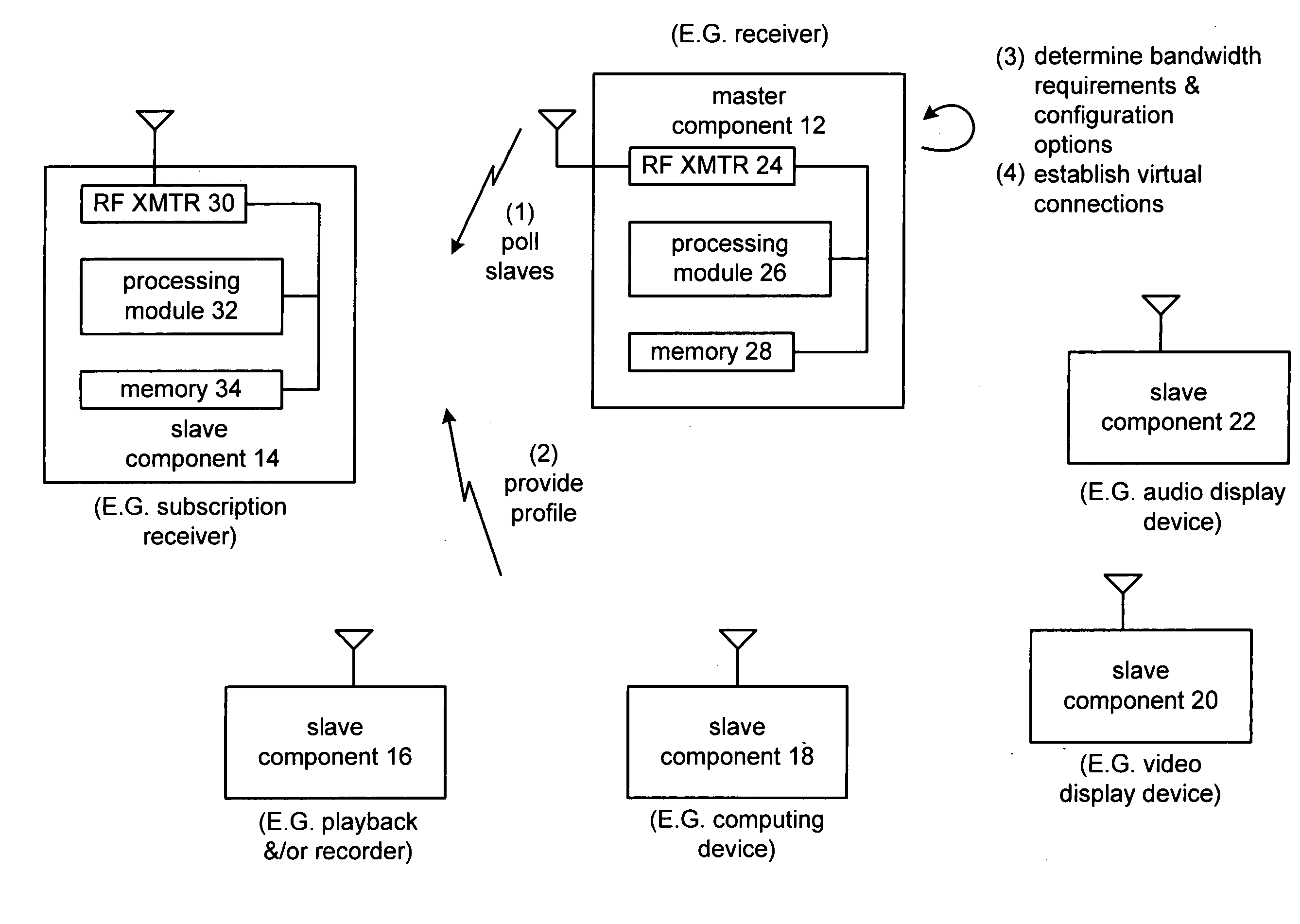
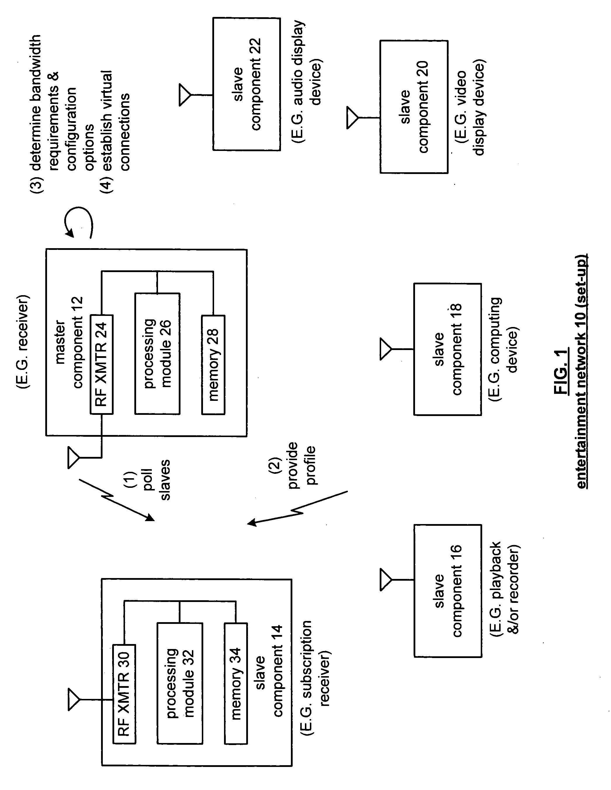
[0022]FIG. 1 is a schematic block diagram of a wireless entertainment network 10 during setup. The entertainment network 10 includes a master component 12 and a plurality of slave components 14-22. The master component 12 includes a radio frequency (RF) transmitter (XMTR) 24, a processing module 26, and memory 28. Slave component 14, which is representative of the other slave components 16-22, includes a radio frequency transmitter 30, processing module 32, and memory 34. The RF transmitters 24 and 30 may be in accordance with one or more wireless communication standards. For example, the RF transmitters 24 and 30 may be constructed in accordance with one or more versions of the Bluetooth standard, one or more versions of IEEE 802.11, et cetera.

[0023] The processing modules 26 and 32 may each be individual processing devices and / or a plurality of processing devices. Such a processing device may be a microprocessor, micro-controller, digital signal processor, microcomputer, central ...


PUM


Abstract

A method for configuring an entertainment network begins by polling, by a master component of the entertainment network, slave components via a communication channel to identify active slave components of the entertainment network. The method continues by providing, by each of the active slave components, a profile response to the master component via the communication channel in response to the polling. The method continues by determining, by the master component, bandwidth requirements and configuration options of the entertainment network based on the profile responses of the active slave components and a profile of the master component. The method continues by, based on the bandwidth requirements and the configuration options of the entertainment network, establishing, by the master component, at least one of: a virtual connection between the master component and at least one of the active slave components and a virtual connection between a first one of the active slave components and a second one of the active slave components.

Description

BACKGROUND OF THE INVENTION [0001] 1. Technical Field of the Invention [0002] This invention relates generally to entertainment systems and more particularly to network-based configurability of such entertainment systems. [0003] 2. Description of Related Art [0004] As is known, entertainment systems have evolved from a television set and a radio to complex systems that include expensive video equipment, computers, satellite receivers, cable receivers, broadcast receivers, expansive audio equipment, video game equipment, DVD players, CD players, etc. Such complex entertainment systems offer its users tremendous variety in home entertainment and movie theater quality. [0005] As is also known, providing the electrical coupling between the components of an entertainment system is done through direct connect wiring. For example, a receiver is typically direct wire coupled to a DVD player, a VCR, a cable set top box, speakers, and a video monitor. Such direct wire coupling includes a sign...

Claims


Application Information

Patent Timeline
Patent Type & Authority Applications(United States)
IPC IPC(8): H04N7/18H04N7/173H04L12/24H04L12/28
CPCH04L12/24H04L12/2803H04L2012/2849H04L41/00H04L2012/2841H04L12/281
Inventor RAEL, JACOBRAEL, HENRY
Owner AVAGO TECH WIRELESS IP SINGAPORE PTE
Learn More