
Insulative panels for a railway boxcar

a boxcar and insulation panel technology, applied in the field of railroad freight cars, can solve the problems of insufficient boxcars to transport over large distances, inability to meet the needs of insulated enclosure floors,

Inactive Publication Date: 2006-03-30
GUNDERSON
View PDF18 Cites 58 Cited by
  • Summary
  • Abstract
  • Description
  • Claims
  • Application Information

AI Technical Summary

Benefits of technology

"The patent describes a new type of boxcar that has insulation on its exterior. This can be added to existing boxcars by attaching insulation panels to the outside. The insulation panels can be attached to the side wall, end wall, or roof of the boxcar, and can be made of rigid material with insulating material in between. This new type of boxcar will help to improve its insulation, making it more comfortable and energy-efficient."

Problems solved by technology

Though the modern boxcar construction just described is adequate to transport heavy loads, such boxcars are often insufficient to transport over large distances perishable cargo or other cargo that must be maintained at a low temperature.
One problem with these existing insulated boxcars is that the floor of the insulated enclosure must be able to withstand without deformation, significant loading both from the cargo carried by the boxcar and the concentrated weight of forklifts or other machinery used to load and unload cargo from the boxcar.
The fiber reinforced composite material, however, does not have the strength of steel, and thus insulated boxcar enclosures are typically fabricated with thicker floors, end walls, and side walls to better withstand the forces encountered during transport of cargo.
Because the exterior dimensions of the boxcar must fit within the assorted plate requirements of the American Association of Railroads (AAR), however, this extra thickness reduces the interior dimensions of the cargo-carrying enclosure of the boxcar, hence decreases the load-carrying capacity of the boxcar.
These refrigeration units are costly to install, and unless used in combination with an existing insulated boxcar with the aforementioned disadvantages, are costly to operate due to the transfer of heat into the interior of the cargo-carrying enclosure.

Method used


Image

  • Insulative panels for a railway boxcar
  • Insulative panels for a railway boxcar
  • Insulative panels for a railway boxcar

Examples


Embodiment Construction

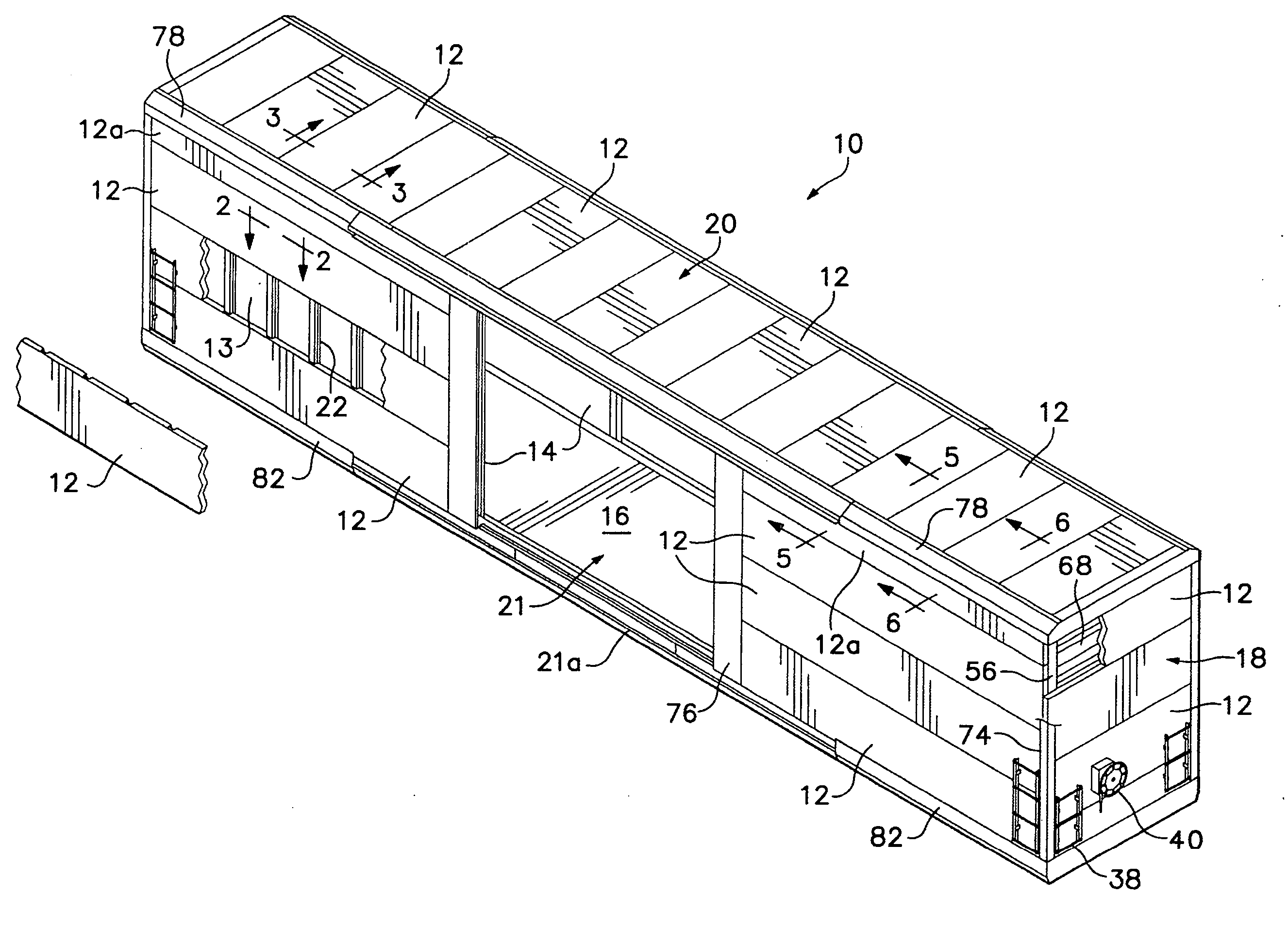
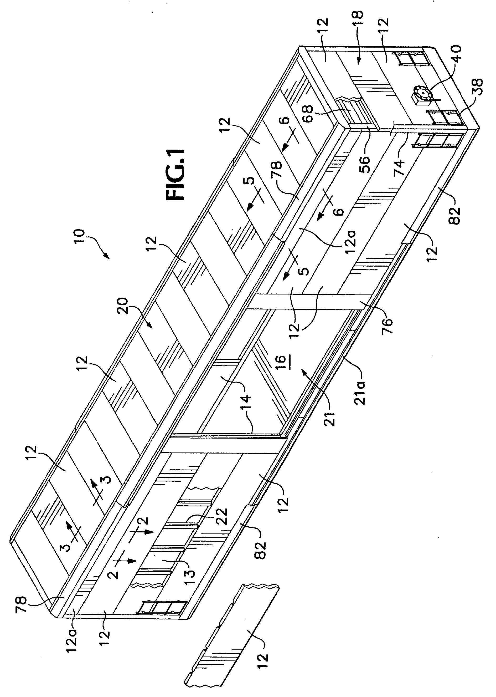
[0020]FIG. 1 shows an exemplary boxcar 10 having opposed side walls 14, opposed end walls 18, a roof 20, and a floor 16, each structurally supported by an undercarriage 15 (shown in FIGS. 4-6) mounted on a truck (not shown) or other member that facilitates movement of the exemplary boxcar 10 along a railroad track. Each of the foregoing side walls 14, undercarriage 15, floor 16, end walls 18, and roof 20 may preferably be fashioned from steel, iron, or other rigid metal members that provide strength to the boxcar 10 and resist deformation of the boxcar due to loading weights and other forces.

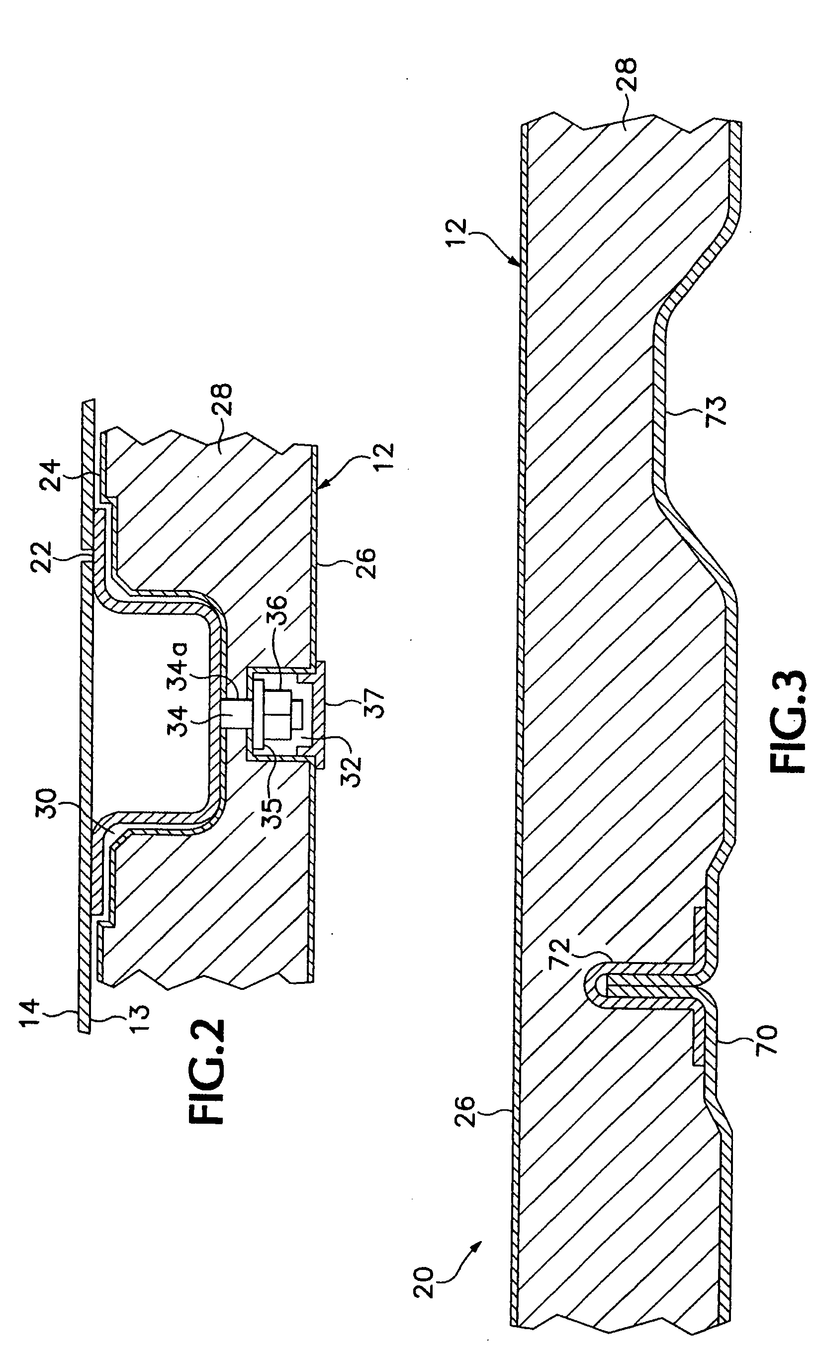
[0021] The side walls 14, end walls 16, and roof 20 of the exemplary boxcar 10 may define an exterior, outwardly facing surface 13 of the boxcar 10 through which a great deal of heat would normally enter during transport of cargo. To insulate the exemplary boxcar 10, and thereby reduce the amount of heat passing through the surface 13, thermally insulative panels 12 may be positioned proximate ...


PUM


Abstract

Insulative panels mountable to the exterior of a railway boxcar, and railway boxcars having exterior insulative panels are disclosed. Each disclosed insulative panel may have first and second skins of fiber-reinforced plastic spaced apart from each other with foam or other insulative material interposed into the space therebetween. The disclosed insulative panels can be attached to the exterior of an existing, non-insulated boxcar to retrofit it as an insulated boxcar. In addition, thermally insulative material may be positioned vertically above a door opening for additional insulation.

Description

CROSS REFERENCE TO RELATED APPLICATIONS [0001] The present application claims the benefit, under 35 U.S.C. § 119(e), of prior provisional application No. 60 / 613,342 filed Sep. 27, 2004 and prior provisional application No. 60 / 651,296 filed Feb. 9, 2005.BACKGROUND OF THE INVENTION [0002] The present invention relates to railroad freight cars and in particular to one or more thermal insulating members for railway boxcars and a method for retrofitting a boxcar to be thermally insulated. [0003] Existing boxcars typically include opposed side walls, opposed end walls, a floor, a roof, and at least one doorway together defining a cargo-carrying enclosure that is mounted upon a supporting undercarriage with a wheel assembly for movement upon a railroad track. Though early railway boxcars comprised simple wooden structures mounted on a platform, modern railway boxcars are built from materials that are both more sturdy and more durable so that they may carry loads far more heavy than what an...

Claims


Application Information

Patent Timeline
Patent Type & Authority Applications(United States)
IPC IPC(8): B61D17/00
CPCB62D33/048B61D17/18
Inventor HEITMEYER, KRISMILITARU, DAN
Owner GUNDERSON
Learn More